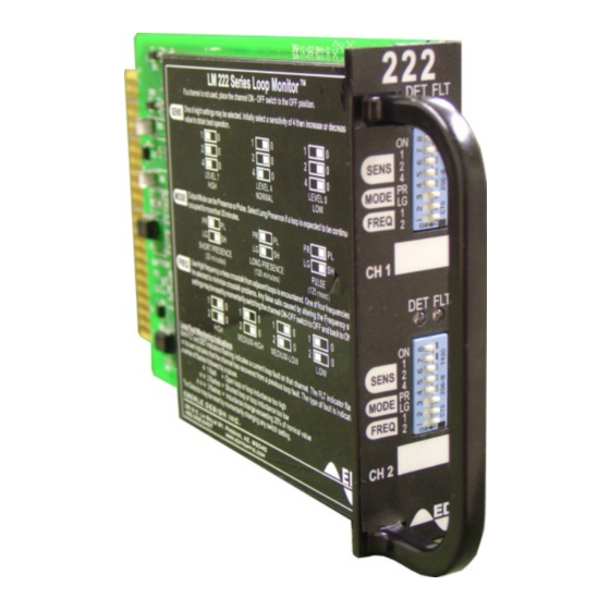
EDI 222 Series Manual de operação - Página 7
Procurar online ou descarregar pdf Manual de operação para Sensores de segurança EDI 222 Series. EDI 222 Series 17 páginas. Inductive loop detector sensor unit

Model 222
Operations Manual
The microcontroller checks the sample to confirm that it is still within acceptable operating limits and
then determines whether the sample has changed sufficiently with respect to the stored reference to
indicate the presence of a vehicle. It then controls the output and indicator appropriately. Small
changes in period which occur over a relatively long time are considered due to the environment and
are tracked out by altering the stored reference. In this fashion, the sensor unit can adjust for
temperature changes and other long term effects such as the expansion and contraction of the
pavement. The microcontroller maintains the time that a channel has been in the presence condition
and will tune out a continuous presence after 30 minutes (Short Presence mode) or 120 minutes
(Long Presence mode).
The microcontroller first determines the status of the front panel switches. The Operational mode
determines whether the detection calls are to be momentary pulse or continuous. The Presence and
the Sensitivity settings determine the length of the sample to ensure that the sensitivity will be
sufficient to detect the desired types of vehicles and that the response time will be correct.
The microcontroller then begins the oscillator period measurement process by energizing the loop
oscillator for the channel to be measured. During period measurement the digital processing circuit
and the microcontroller count the number of cycles of the crystal based reference frequency.
When the sample period ends, the count is compared with a stored reference and detection decisions
are made. Small changes which occur over a relatively long period of time are considered due to the
changing environment, and the stored reference is modified accordingly by the microcontroller. Larger
changes are deemed to be caused by the presence of a vehicle or vehicles and a detection signal is
initiated.
Detection output calls are made via optically isolated transistors. These isolate the traffic controller
input from the sensor unit circuitry. Output calls are indicated on the front panel by means of high
intensity LEDs labeled "DET".
1.6.2 DESCRIPTION OF CIRCUIT OPERATION
The following description is valid for both channels of the Model 222. Reference designators are
shown for channel 1 with those relating to channel 2 in parentheses.
Each loop oscillator is based upon two transistors, Q8 (Q9) and Q11 (Q13), loop transformer T1 (T2)
and primary capacitor C11 (C12). The oscillator is enabled by transistor Q7-A (Q7-B). Frequency
modification capacitors C17 and C15 (C18 & C16) are switched in via Q10-B (Q12-B) and Q10-A
(Q12-A). Transient protection is provided by surge arrestor CR5 (CR6). When loops are connected to
the loop input terminals and the unit is under power, the oscillators will attain their natural frequency
according to the inductance of the loop and the capacitance which has been added via the frequency
modification capacitors.
The oscillator output signal is found on the collector of Q8 (Q9) and is sine wave at the oscillator
frequency (while the oscillator is energized). Zener diodes CR13 (CR14) are used to limit any voltage
surges which may appear on the circuit side of the loop transformer.
The loop frequency signals from both of the oscillators are fed into Schmitt circuits U5A (U5B) to form
square wave signals. The outputs of the Schmitt triggers are fed into the digital processing circuitry
integrated into the microcontroller.
The digital processing circuit determines the period of a predetermined number of loop oscillator
cycles and stores this value for retrieval by the microcontroller firmware. This value represents the
period of the loop oscillator waveform to a very high precision.
Eberle Design Inc.
Page 5
