AIMS Power PWRIG150012120S Manual de operação - Página 11
Procurar online ou descarregar pdf Manual de operação para Inversor AIMS Power PWRIG150012120S. AIMS Power PWRIG150012120S 16 páginas.

Important:
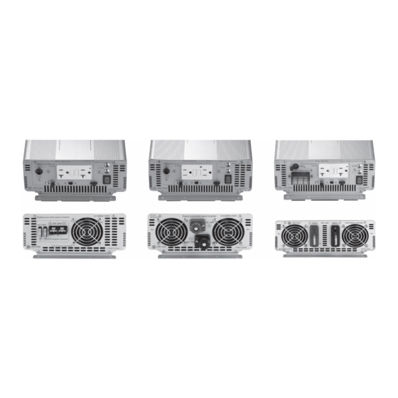
Locate the number below to the number on Front or Back of the inverter on the Overview page 10.
1) Input Terminal (12V, 24V or 48V)
Prior to any connections make sure you match the battery Voltage to the inverter input Voltage. You will probably notice an arc when
connecting a discharged or new power inverter to your batteries. Make sure to connect battery (-) to Black and battery (+) to Red. Tighten
terminals. In case of extreme vibration, go back and verify terminals are tight.
Tip: when connecting multiple 12Vdc batteries, connect all the Red (+) together and all the Black (-) together. This will keep the input
Voltage at 12Vdc. Never connect batteries with different Voltages unless you are certain of what you are doing.
2) Power Switch
This is the main unit Power Switch. When this is turned OFF, the inverter is off. When turned ON, the inverter is on. You may or may not
have 120 V AC out, depending on the two Protection Switches.
3) Overload Protection LED's
When the inverters self-tests process completes, this red LED will illuminate. If this red LED is off, an internal error is indicated. First you
will hear a buzzer, followed by this LED being illuminated. You should immediately turn off all of your equipment. The LED will
automatically reset once the overload situation has been resolved. The overload may be caused by one or more of the following:
Short circuit on AC line
An actual overload occurred exceeding the inverters output power
Over Temperature
Low battery Voltage
High battery Voltage
4) AC Voltage Source (this may be 110 or 120VAC 60Hz for US market)
Please make sure no other power source can ever feed back into these outlets. It will permanently damage the inverter and void the warranty
5) Automatic Fan Operation
These fans are thermally controlled and will turn on automatically when needed
11
