Altronix TMV2 Manuais de instalação - Página 4
Procurar online ou descarregar pdf Manuais de instalação para Invólucro Altronix TMV2. Altronix TMV2 16 páginas. Access & power integration
Também para Altronix TMV2: Manuais de instalação (16 páginas), Manual de instalação (4 páginas), Manual de instalação (20 páginas)
Altronix Power Supplies/Chargers and/or Sub-Assemblies:
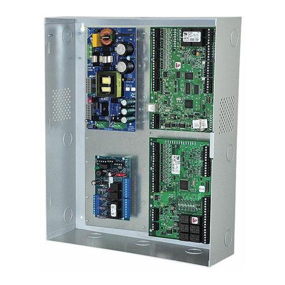
1. Fasten standoffs (provided) to pems that match the hole pattern for Altronix Power Supply/Chargers or Altronix Sub-Assembly boards
(positions (B) and (C), Fig. 2, pg. 4). Use snap on nylon standoffs for the upper two mounting holes in the board.
Use metal standoffs for the bottom mounting holes to provide sufficient grounding for the board.
2. Affix boards to standoffs (Fig. 2a, pg. 4) by pressing down the upper mounting holes onto nylon standoffs.
Use provided mounting screws to affix the lower mounting holes. Make sure that boards are locked onto standoffs.
3. For detailed information about installing and connecting Altronix sub-assemblies refer to the individual Installation Instructions listed in the
Sub-Assembly Position Chart, pg. 3 and Trove Installation Guide, Rev. 101817.
Lenel Sub-Assemblies:
4. Fasten standoffs onto metal pems configuration (A), (D), (E) or (G) of enclosure depending on the sub-assembly module (Fig. 2, pg. 4).
5. Position access controller module over corresponding standoffs and depress onto snap on standoffs (Fig. 2a, pg. 4).
6. Fasten backplane to Trove1 enclosure utilizing lock nuts (provided).
Fig. 2
A
D
A
E
Trove / Lenel
Installation Instructions for Sub-Assemblies to TM1:
F
B
A
A
G
C
C
D
G
E
Fig. 2a
Pem
Snap on or
Metal
Standoff
Backplane
Sub-Assembly
- 4 -