CVI SDX Manual - Página 3
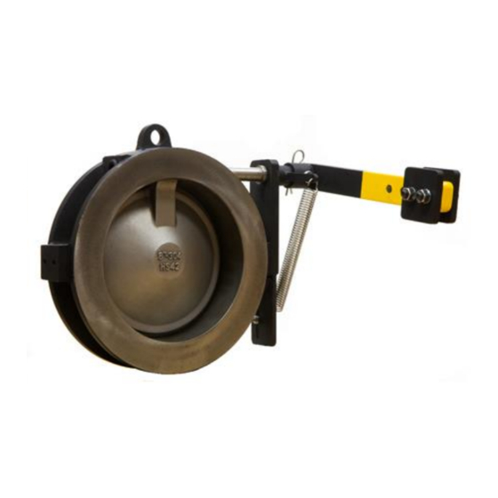
Procurar online ou descarregar pdf Manual para Unidade de controlo CVI SDX. CVI SDX 7 páginas. Single disc external spring check valve
The valve should be securely held in place by banding or other means of support to prevent accidental
damage due to movement of the valve.
For outdoor storage, special crating and valve preparation can be provided, at an additional charge,
based upon specific requirements for each situation. Periodical checks at least every 6 months have to
be carried out in the storage area to verify that the above mentioned conditions are maintained.
Handling:
Most valves are supplied with a removable lifting eye. Always lift the valve using this device, as damage
to the valve body or threads (if applicable) could occur from improper lifting. Alignment and final
installation should be done while the valve is being supported by the lifting eye.
The valve should never be used as an alignment point in the pipeline. Be sure the pipeline flanges on
both sides of the valve are aligned with the proper spacing before the valve is installed into the system.
Never lift or move the valve assembly by using the body rim, external springs or levers (if supplied),
valve disc or mounting holes.
Transport, unpack and store being careful not to scratch the surfaces of flanges or gaskets. Also, take
steps that will prevent any foreign matter from getting into the valves. Wooden plate or plastic caps
should not be removed until the valves are installed.
The transportation of all packed material must be carried out safely and following the local safety
regulations.
INSTALLATION
1. Remove the valve from carton or packing skid.
2. The protective rust proof coating on the internal parts of steel or cast iron valves should be removed
by brushing out with any standard petroleum solvent (Varsol, Kerosene) and air dried. Insure
internal parts operate freely.
3. Stainless Steel or Bronze valves need only to be wiped clean and installed.
4. In horizontal flow installation, the hinge shaft must be horizontal.
5. Insert the valve between two companion flanges of the same series as the valve and place gaskets
on flange faces. The arrow on the valve or name plate indicating direction of flow should coincide
with line flow. Install studs through companion flanges and tighten, using standard industry
practice.
6. We recommend valve be installed at least five (5) pipe diameters downstream from a pump
discharge and/or other pipe fittings for maximum service life.
P.O. B
12901, WILMINGTON, NC 28405
OX
P
: 910-794-5547 - F
HONE
W
:
.
EBSITE
WWW
WAFERCHECK
: 910-794-5581
AX
.
COM