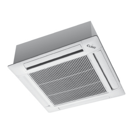
Clint TCW 104 Manual de instruções de instalação, utilização e manutenção - Página 5
Procurar online ou descarregar pdf Manual de instruções de instalação, utilização e manutenção para Ar condicionado Clint TCW 104. Clint TCW 104 11 páginas.
Também para Clint TCW 104: Manual de instalação, utilização e manutenção (10 páginas)

2.7 Conexiuni electrice
Inainte de efectuarea oricaror operatii pe partea electrica,
deconectati-va de la sursa principala de energie prin actionarea
intrerupatorului general. Conectati intodeauna cablurile pentru
impamantare.
Impamantarea este obligatorie prin lege.
Instalatorul trebuie sa utilizeze terminalul cel mai apropiat care este
marcat cu simbolul international pentru impamantari.
UNITATE PENTRU SISTEME CU 2 SAU 4 TEVI: MODELELE 42÷54
Schema de montaj: aceasta varianta furnizata din fabrica poate sa
contina modificari. Utilizati intotdeauna schema livrata cu produsul
achizitionat.
Unitate pentru sisteme cu 2 tevi, cu
sau fara vane, cu panou de
comanda DRM.
BLOC TERMINAL
Unitate pentru sisteme cu 2 tevi, cu
sau fara vane, cu panou de
comanda DRA.
BLOC TERMINAL
PE
L
N
3
1
Q1
2
4
~230 V 50 Hz
CV
Condensator / Condenser
FCA
Siguranta automata / Automatic protection
FCM
Siguranta manuala / Manual protection
KH
Relee de alarma / Alarm relais
L
Faza / Phase
Motor pompa evacuare condens
MP
Drain pump motor
MV
Motor ventilator / Fan motor
N
Nul / Neutral
Unit for system with 2 pipes, with
or without valve, with DRM con -
trol panel.
N L
Unit for system with 2 pipes, with
or without valve, with DRA control
panel.
N L
230 Vac
SM
PCB
Tablou electronic / Electronic board
PE
Impamantare / Ground
Q1
Protectie / Protection
R1/R2
Baterie electrica / Electric heater
SB1/SB2 Sonda nivel apa / Water level sensor
SM
Sonda temp. minima apa / Sensor min. water temp.
TV
Autotransformator / Autotransformer
X
Bloc terminal / Power terminal block
YC
Vana cu 3 cai (4 T) / 3-way valve (4 T)
YF
Vana cu 3 cai / 3-way valve
2.7 Electrical connections
Before performing any work on the electrical part of the unit, turn off the
main switch. Always remember to connect the earth wire.
Earth connection is obligatory by law.
The installer must provide for it via the terminal marked with the interna-
tional earth symbol.
UniT FoR 2 AnD 4 pipes sysTem: moDels 42÷54
Main layout: the variants made in the constructions can involve modifi -
cations. Always refer to the layout supplied with the product.
Unitate pentru sisteme cu 4 tevi cu
doua vane, sau sistem cu 2 tevi, cu
sau fara vane, cu panou de
comanda DRA.
BLOC TERMINAL
PE
L
N
1
3
Q1
2
4
~230 V 50 Hz
R1 R2
MV
FCM
CV
21
11
22
12
M
TV
KH
6
PE
L
N
3 4 5
1
3
Q1
2
4
230V-50Hz
YC
Unit for system with 4 pipes, with
two valves, or with 2 pipes, with or
without valve and electric heater,
with DRA control panel.
3 4 5
16 17 18
A1
KH
A2
MP
FCA
SB1
SB2
M
1 L
7
1
YF
viteza minima
minimum speed
min
/
med
viteza medie
medium speed
/
max
viteza maxima
maximum speed
/
N L
230 Vac
SM
PCB
A1
KRX
A2
6
2 X
