Clippard EVPD Manual de instalação e operação - Página 2
Procurar online ou descarregar pdf Manual de instalação e operação para Accionamentos DC Clippard EVPD. Clippard EVPD 3 páginas. Proportional valve driver
Section 2 Tuning
Tuning Parameters
1.0
0.9
0.8
0.7
0.6
0.5
0.4
0.3
Command Threshold
0.2
When the Command
Signal is less than this
0.1
value, the Driver
output current is zero
0
0
2
4
Command Signal (0 to 10 VDC for this example)
Step 1b:
Turn DB clockwise until Status Indicator LED (green)
turns Off. Then turn counter-clockwise just enough to turn
the LED On
Status Indicator LED (green) will be On at first
Turn DB (RP1) clockwise until Status LED is Off
Turn DB counter-clockwise just enough to turn the Status
Indicator LED (green) On
* The 0.1 VDC value for the Command Threshold is a minimum value that may be increased according to the needs of the application, therefore the Command Signal
values given in steps 1 and 2 are given as minimum values, not as the only possible values.
WARNING: Installation and operation of electronic and high pressure systems (fluids and
compressed gas) involves risk including property damage and personal injury or death.
Users should be properly trained or certified and take safety precautions.
lmax
The output current of the Driver
when the Command Signal is at
maximum value
lmin
The output current of the Driver
when the Command Signal just
exceeds the Command Threshold
6
8
10
Status Indicator LED
Status Indicator LED
Status Indicator LED
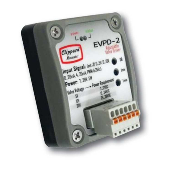
EVPD PROPORTIONAL VALVE DRIVER
Installation & Operations Manual
Step 2:
Adjusting Opening Current
This will assure the valve opens at just above the
minimum Command Signal.
Step 2a:
Connect supply air to the valve
Step 2b:
Apply a Command Signal according to the table
below to the drive (same as
Command Range
Min. Command Signal*
12
Step 2c:
Turn Imin
clockwise until valve opens
Step 3:
Adjusting Max Current
This will assure that the maximum Command corresponds to
maximum desired flow
Step 3a:
Apply maximum Command Signal according to the
table below to the driver
Command Range
Command Range
Signal to Apply
Signal to Apply
Step 3b:
Turn Imax clockwise to
increase flow to desired maximum. To
reduce maximum flow, turn Imax
counter-clockwise to below the target
flow, then clockwise to the desired
maximum.
Δ
!
Caution: Do not exceed the
maximum current of the DVP/EVP valve
or permanent damage may occur to the valve.
Step
1)
0 to 5 VDC
0 to 10 VDC 4 to 20 mA 0 to 20 mA
0.1 VDC
0.1 VDC
Step 2d:
Turn Imin slightly
counter-clockwise until
valve barely closes
Current
Min.
0 to 5 VDC
0 to 10 VDC
4 to 20 mA
5 VDC
10 VDC
20 mA
877-245-6247 |
CLIPPARD INSTRUMENT LABORATORY, INC. • ISO 9001:2015
4.2 mA
0.2 mA
Current
Min.
0 to 20 mA
20 mA
Current
Max.
clippard.com