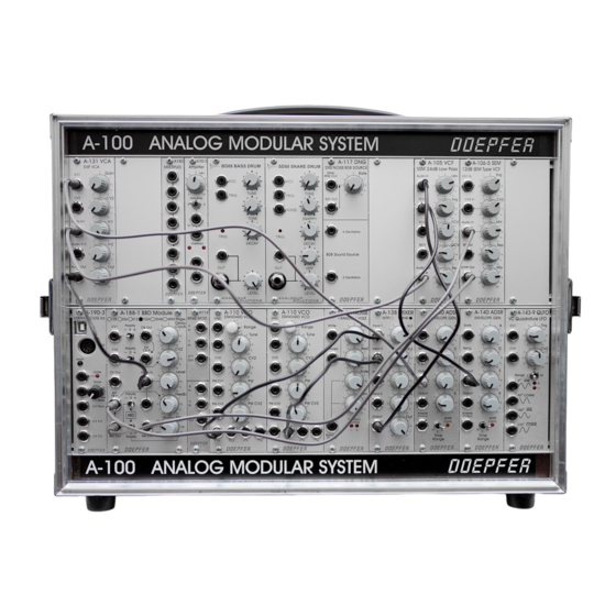
For small DIY set-ups with up to eight modules and a maximum of 380 mA supply
current the A-100SSB (small supply/bus board) is intended. A-100SSB is the
combination of a small power supply (+12V/max. 380mA, -12V/max. 380mA) and a
bus board with 8 connectors for A-100 modules.
A slightly modified version of the A-100SSB is used also in the case A-100LC1: the
supply and bus unit of the A-100SSB are separated and connected via cables.
That's why there is a common user's guide for both units.
The power supply provides the voltages +12V and – 12V required to run the A-100
modules. In addition +5V are available which are required for some older A-100
modules and modules from other manufacturers.
The maximum current load is 380 mA for +12V, 380 mA for -12V, and 50 mA for
+5 V. If +5V is used the current is taken from the +12V source. In this case the
currents for +12V and +5V have to be added and the sum has to be not more than
380mA.
The A-100SSB/A-100LC1 bus provides connections for up to eight A-100 modules or
modules from other manufacturers which are 100% compatible. The busboard also
carries the internal signals CV and GATE which may be used if required. This
depends upon the installed modules and if they use the interal CV and/or Gate lines
(e.g. Midi/USB interfaces, VCOs, ADSRs).
The pc board includes a switching power supply module that converts the incoming
mains voltage (110 – 240V AC) into the low voltages (+12VDC, -12VDC) required to
run the A-100 modules.
Important safety notes
A-100SSB/A-100LC1 is equipped with an IEC socket to establish the connection to
mains by using a suitable cable. During operation dangerous voltages are present at
the bottom of the pc board ! For this reason a metal cover is located at the bottom of
the pc board which prevents the touching of the dangerous parts of the circuit.

