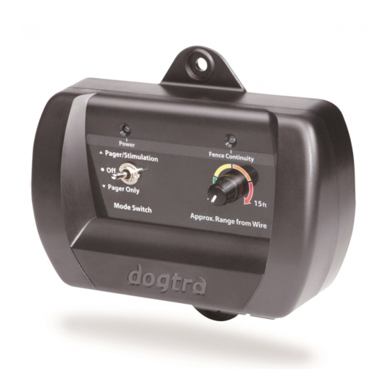
Dogtra E-Fence 3500 Manual do Proprietário - Página 5
Procurar online ou descarregar pdf Manual do Proprietário para Sistemas de controlo Dogtra E-Fence 3500. Dogtra E-Fence 3500 16 páginas.

Boundary Wire Continuity Light
Wire Connector Tabs
wire to ground the unit. Strip about a half-inch on each end of the
ground wire and insert one end into the black connector on the
bottom of the wall transmitter. The other end should be buried
into the ground or wrapped around a water pipe and secured with
electrical tape.
Option : A lightning/surge protector can be purchased if there are
no grounding options near the wall transmitter.
8
When the wires are connected
properly, the boundary wire
continuity light will be on.
In the event that the E-Fence
3500 wire becomes damaged
or disconnected, the light will
automatically turn off and the
warning beep will sound.
The easy-to-use push-release
wire connectors let you instantly
connect or disconnect the
boundary wire leads. Wires
should have the plastic coating
stripped approximately a half-
inch before being inserted into
the red connectors on the bottom
of the wall mount transmitter.
The system comes with a ground
Power Jack
Wall-Mount Transmitter
Use the (2) included screws to mount the transmitter to a wall
securely near an outlet. The unit will withstand freezing
temperatures, but it is not waterproof. Therefore, we recommend
mounting the transmitter in a safe, dry sheltered area such as a
shed, garage or carport. Plastic anchors have been provided to
secure mounting onto drywall. Use a 1/4" drill bit to make holes
into the drywall. Insert the anchors into the holes so that the open
end faces out and mount the transmitter by inserting the screws
into the open end of the anchors.
To power the wall transmitter, plug the power adaptor into a
standard 120-volt outlet and connect it to the power jack of the
transmitter.
Plug the 120-volt adaptor into a
120-volt wall outlet and insert
the adaptor plug into the power
jack of the transmitter.
9
