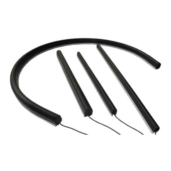
Cyndar Electronic Technology HL-1612 Manual do produto - Página 7
Procurar online ou descarregar pdf Manual do produto para Instrumentos de medição Cyndar Electronic Technology HL-1612. Cyndar Electronic Technology HL-1612 14 páginas. Safety edge sensor

(2) Wiring configuration
Determine the wiring configuration according to the number of safety contact edges (sensors) connected in
series. (Up to 5 safety contact edges can be connected in series)
Configure Number
Outline drawing
2-wire cable
1
2-Line cable,
2
2-wire cable
3
Controller configuration example 1
Use a safe touch edge
2-wire cable
Safe touch
Controller
2-wire cable
Safe touch
Controller
PLC configuration example 2
Secure edge and PLC connection mode
PLC
PLC
Normally open wiring:
①Line No. is connected to the power supply or the negative pole of PLC
②Line No. is connected to PLC emergency stop input signal interface
Normally closed wiring:
③Line No. is connected to the power supply or the negative pole of PLC. (Connect with the COM interface of the relay)
④Line No. is connected to the PLC emergency stop output signal interface (connected to the NO interface of the relay
⑤⑥Line No. is connected to the input terminal of the relay signal (regardless of the positive and negative poles)
Safe touch
2-Line cable
Safe touch
Terminalresistance
Safe touch
Use N safe touch edges
2-wire cable
connection
Safe touch
Controller
2-wire cable
connection
Safe touch
Controller
①
②
③
Relay:
④
Output Type
NO
NO
NO
Safe touch
Safe touch
Safe touch
Safe touch
Safe touch
⑤
⑥
Wiring configuration
One-end outgoing line 2-line cable (2-
line system)
Two-line outgoing line cable at both
ends (4-line system)
One end outgoing line 2 line cable (2
line system) and end resistance at the
other end (8.2KΩ 0.25W)
Terminating resistor
Safe touch
7
