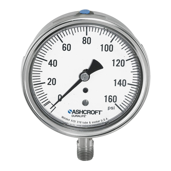
Ashcroft 1082 Manual de instalação, operação e manutenção - Página 11
Procurar online ou descarregar pdf Manual de instalação, operação e manutenção para Instrumentos de medição Ashcroft 1082. Ashcroft 1082 20 páginas. Pressure gauge

6.1 Calibration – Rotary Movement Gauges
– Inspect gauge for accuracy. Many times
gauges are simply "off zero" and a simple
pointer adjustment using the micrometer
pointer is adequate. If inspection shows the
gauge warrants recalibration to correct span
and/or linearity errors, proceed as follows:
a. Remove ring, window and, if solid front
case, the rear closure assembly.
b. Pressurize the gauge once to full scale and
back to zero.
c. Refer to Figure 2 on page 8 for a view of a
typical Ashcroft system assembly with
component parts identified.
d. For solid front gauges, adjust the microme-
ter pointer so that it rests at the true zero
position. For open front gauges the pointer
and dial must also be disassembled and
the pointer should then be lightly pressed
onto the pinion at the 9:00 o'clock position.
e. Apply full scale pressure and note the
magnitude of the span error. With open
front gauges, ideal span (270 degrees) will
exist when at full scale pressure the point-
er rests exactly at the 6:00 o'clock position.
f. If the span has shifted significantly (span
error greater than 10%), the gauge should
be replaced because there may be some
partial corrosion inside the bourdon tube
which could lead to ultimate failure. If the
span error exceeds 0.25%, loosen the lower
link screw and move the lower end of the
link toward the movement to increase
span or away to decrease span. An adjust-
ment of 0.004 inch will change the span by
approximately 1%. This is a repetitive pro-
cedure which often requires more than one
adjustment of the link position and the
subsequent rechecking of the errors at zero
and full scale pressure.
g. Apply midscale pressure and note error in
reading. Even though the gauge is accu-
rate at zero and full scale, it may be inac-
curate at the midpoint. This is called lin-
earity error and is minimized by rotating
the movement. If the error is positive, the
movement should be rotated counter clock-
wise. Rotating the movement one degree
will change this error by approximately
0.25%. Rotating the movement often
affects span and it should be subsequently
rechecked and readjusted if necessary
according to step 6.1e and 6.1f.
h. While recalibrating the gauge, the friction
error – difference in readings taken with
and without rap – should be noted. This
error should not exceed the basic accuracy
of the gauge. If the friction error is exces-
sive, the movement should be replaced.
One possible cause of excessive friction is
improper adjustment of the hairspring.
The hairspring torque,or tension, must be
adequate without being excessive. The
hairspring should also be level, unwind
evenly (no turns rubbing) and it should
never tangle.
NOTES:
1 For operation of test gauge external zero
reset, refer to Figure 3 on page 12.
2 For test gauge calibration procedure,
refer to Figure 4 on page 13.
6.2 Calibration – 1009 Duralife
Inspect gauge for accuracy. Many times
gauges are simply "off zero" and a simple
pointer adjustment using the adjustable
pointer is adequate. If the inspection shows
that the gauge warrants recalibration to cor-
rect span and/or linearity errors, proceed as
follows:
Remove ring, window, gasket and pointer
using Ashcroft tool kits 1205T and 1206T.
6.3 Positive Pressure Ranges –
a. Remove dial and lightly press pointer onto
pinion at 9:00 o'clock position.
b. Apply full scale pressure and rotate span
block as shown in Figure 5a on page 15
until pointer rests at 6:00 o'clock position.
c. Fully exhaust pressure and check that
pointer still is at 9:00 o'clock position. If
not repeat steps 1 and 2 until span is
correct.
(Continued on page 10)
11
®
Gauge –
