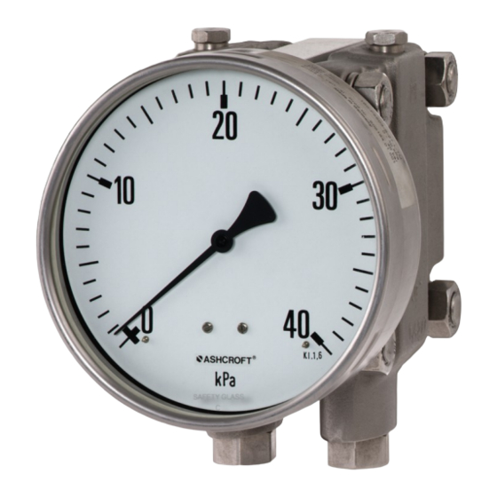
Ashcroft F5503-XSP Manual de instruções de instalação e manutenção - Página 4
Procurar online ou descarregar pdf Manual de instruções de instalação e manutenção para Instrumentos de medição Ashcroft F5503-XSP. Ashcroft F5503-XSP 7 páginas. Differential pressure gauges

Installation and Maintenance Instructions for
5503 Differential Pressure Gauges
7.3 Mounting/Installation
7.3.1 Process connection
The instrument is intended and factory adjusted for vertical
mounting, pressure ports downward. When mounted in other
orientation (max. ± 10°) the pointers' zero position needs to be
adjusted (see 7.4.1 Zero point adjustment).
• Connection to be undertaken by authorized and qualified
staff specialist only.
• Use only with the mechanical process connection provided
– regarding the configuration, see order code on the device
type label, with a matching threaded seal.
• When connecting the device, the pipes must be
depressurized.
• The pressure metering pipe must be laid inclined in such
a way that, for example, for measurements of fluids no air
pockets can form, and for measurements of gases no water
pockets. If the necessary incline is not achieved, then at
suitable points water separators or air separators must be
installed.
• The pressure metering pipe must be kept as short as possible
and laid without sharp bends, to avoid delays.
• The instruments pressure ports are marked by "+" and "-"
symbols:
"+" port must be connected to the higher pressure
"-" port must be connected to the lower pressure.
• With liquid measurement media, the pressurized connection
pipe must be degassed, since any gas bubble inclusions
result in measurement error.
• If water is used as the measurement medium, the device
must be frost-protected.
Safety notice: Only mount using the correct
open-jawed wrench, and do not twist the
device itself.
7.3.2 Electrical connection
Take note of the electrical data in the EU design type test cer-
tification and the locally-applicable regulations and
guidelines for installing and
operating electrical plant in explosion risk areas
(e.g. EN 60079-14, EN 50281-1-2 etc.).
• Connection to be undertaken by authorized and qualified
staff specialist only.
• The electrical connection of the device is to be undertaken in
accordance with the relevant regulations of the VDE and the
regulations supplied by the local utilities company
• Disconnect the equipment from the power supply before
wiring electrical connections.
• Install appropriate fuses upstream.
© Ashcroft Inc. 2019, 250 East Main Street, Stratford, CT 06614-5145, USA, Tel: 203-378-8281, Fax: 203-385-0357, www.ashcroft.com
All sales subject to standard terms and conditions of sale. 5503_gauge_i&m_RevA_07-18-19
7.4 Starting up
The precondition for start-up is proper installation of all
electrical feed lines and metering pipes. All connecting lines
must be installed so that no mechanical forces can act on the
device. Before start-up, the seal on the pressurized connection
line must be leak checked.
7.4.1 Zero point adjustment
The differential pressure gauge is factory adjusted therefore in
normal case adjustment during installation is not necessary. On
this devices zero point adjustment on site is possible. For this,
proceed as follows:
• Equalize pressure in both chambers.
• Disassemble screw plug
• Use zero point adjustment screw to set the pointer to zero.
• Mount screw plug
7.4.2 Setting the electric contacts
An adjustable lock is fitted in the front panel of the pressure
gauge. Using the removable adjustment key, the contacts
mounted on the target value indicators can be set to any
point on the range covered by the scale. For reasons relating
to accuracy of switching and the lifetime of mechanical
measurement systems, the switch points should be positioned
between 10% and 90% of the range.
• Place the adjustment key on the axle of the adjustable lock.
• Press the axle inwards, until the carrier arm grips behind the
.
adjuster pin on the target value indicator.
• By turning the key, adjust the target value indicator to the
desired switch point.
Release the pressure on the axle, and remove the adjustment
key.
Please refer
to the label
for configuration
of connections.
Filled Models need to be vented before
commissioning by opening the air valve on the
upper side of instrument!
4
