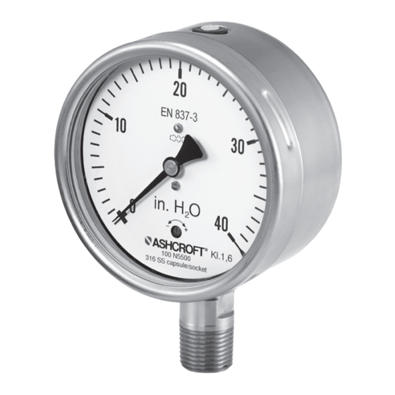
Ashcroft N5500 Instruções de instalação e manutenção - Página 2
Procurar online ou descarregar pdf Instruções de instalação e manutenção para Instrumentos de medição Ashcroft N5500. Ashcroft N5500 3 páginas. Capsule pressure gauge
Também para Ashcroft N5500: Manual de instruções de instalação e manutenção (8 páginas)

Installation and Maintenance Instructions for
N5500 Capsule Pressure Gauges
2.4 Operator qualifications
The device may only be installed and started by operators
who are familiar with installation, start-up and operation of the
product.
2.5 Signs/Safety markings
The N5500 and its surrounding packaging carry markings.
These markings show the article number, measurement range
and manufacturer. The N5500 can be provided with additional
signs and safety markings advising on special conditions:
n Advice on the filling liquid
n Advice on calibration
n Safety marking pursuant to EN 837-3
n Silicone-free
2.6 Safety Equipment
This N5500 is fitted with a rear wall or plug capable of being
blown out. For a description, please refer to Chapter 6.3.4.The
window of model N5500 uses instrument glass (optional multi-
layer safety glass).
3 TECHNICAL DATA
Detailed technical information and data sheet is available from
the Ashcroft website. Please visit www.ashcroft.com.
4 CONSTRUCTION AND FUNCTION
The label with the serial number and type designation is located
on the outside of the housing. The materials identifier is encod-
ed in the type designation.
4.1 Overview
1
2
3
4
4.2 Description of function
The sensing element is a capsule which consists of two
diaphragms that are assembled pressure tight at the edge.
The pressure is led to the central point of the diaphragm and
© Ashcroft Inc. 2019, 250 East Main Street, Stratford, CT 06614-5145, USA, Tel: 203-378-8281, Fax: 203-385-0357, www.ashcroft.com
All sales subject to standard terms and conditions of sale. n5500_gauge_im_RevA_03-10-21
1. Case
2. Capsule
5
3. Process medium
6
4. Process connection
5. Window
7
6. Dial
8
7. Pointer
8. Bayonet Ring
acts on the inside of the capsule. The hereby produced lifting
movement is a measure for the pressure.
4.3 Description of components
4.3.1 Scale with pointer
The pressure gauge is equipped with a dial face and pointer
pursuant to EN 837-3, nominal size 100 mm or 160 mm.
4.3.2 Instrument connection
The instrument connection is located on the bottom, side or at
the back side of the pressure gauge.
4.3.3 Vent valve
The vent valve for the housing is located on the top side. If the
nipple is pulled out, the housing is ventilated and the pressure
which has built up in the housing due to the influence of
temperature is discharged. With the valve closed, protection
class IP 65 is achieved.
4.3.4 Rear wall/plug with blow-out capability
The pressure gauge has a plug capable of blowing out on
the rear wall of the housing. These act as a safety feature
pursuant to EN 837-3 and simultaneously allow for temperature
compensation for the housing, via a rubber membrane.
4.4 Accessories
Please contact the manufacturer regarding special tools and
accessories.
5 TRANSPORT
5.1 Safety
The N5500 should be protected against the effects of knocks
and impacts. The device should only be transported in the
packaging provided, to protect against glass breakage. The
N5500 should only be transported in a clean condition (free of
residues of measuring media).
5.2 Inspection
Upon receipt, the N5500 should be checked for any possible
damage that may have occurred during transport. In the event
of damage during transport, the delivery must not be accepted.
5.3 Storage
The N5500 must be stored in dry, clean conditions, within a
temperature range of -40 to +158°F, protected against direct
exposure to sunlight and protected against impact damage.
6 ASSEMBLY/INSTALLATION
6.1 Safety
To ensure safe working during installation and servicing,
suitable shut-off valves should be installed in the plant to allow
for:
• Gauge to be depressurized or taken out of operation;
• Gauge to be disconnected from the mains supply for repair or
checks within the plant.
• Gauge to be tested as part of standard maintenance.
During the works to mount/install the gauge, the plant must be
protected against being switched back on.
2
