Cypress EZ-PD CY4533 Manual - Página 13
Procurar online ou descarregar pdf Manual para Placa-mãe Cypress EZ-PD CY4533. Cypress EZ-PD CY4533 20 páginas. Barrel connector replacement (bcr) evaluation kit

Voltage on VBUS is 20% below the VBUS_MIN setting or 20% above the VBUS_MAX setting.
When the Type-C power adapter cannot provide the voltage or current set in the selector pins, the BCR part negotiates for
5V at 900mA and turns ON the Safe 5V Load Switch (Q2 on the EVK).
A system can use this voltage to either run in reduced feature mode or notify you that an incompatible power adapter is
attached.
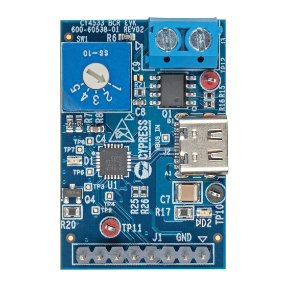
2.3.5 8-Pin I/O Header
The CY4533 EVK has an 8-pin header (J1) that exposes a few pins, the internal 3.3V rail generated by the BCR device, and
ground pins for debug use.
The HPI pins (HPI_SCL and HPI_SDA) are connected to an I2C slave on the BCR at address 0x08 (7-bit). Host Processor
Interface (HPI) is a proprietary protocol on top of I2C that exposes control and status registers of the BCR device. See the
BCR datasheet
for details about this interface.
The FLIP pin can be used to detect the orientation of the Type-C cable connection (right-side-up or upside-down). The FLIP
pin is a simple push-pull output from the BCR that indicates if the Type-C power adapter was attached right-side-up (FLIP =
0V) or upside-down (FLIP = 3.3V). The polarity of this signal can be used to control a Multiplexer for flipping the USB signals
in an application that is a Power Sink and Data Host/Device.
2.4 Changing VBUS Voltage and Current Requested from Power Adapter
The BCR controller executes a capability matching algorithm to select the best voltage and current from the attached USB
Type-C power adapter.
Internally, the BCR maintains a Sink Capabilities list based on the VBUS voltage and current selector pins. See
for the capabilities.
Field in the PDO
Type of PDO (Power Delivery Object)
Min Voltage
Max Voltage
Current
If the VBUS_MIN value is higher than 5V, then the "Higher Capability" bit is set in the first Sink Power Delivery Object
(PDO). This tells the Type-C power adapter that voltages higher than 5V are needed by the system.
The capability matching algorithm works as follows:
Loop through the power adapter's source PDOs from highest voltage first to find the first PDO that satisfies the following
1.
conditions:
Source_PDO_Voltage ≥ VBUS_MIN
a.
Source_PDO_Voltage ≤ VBUS_MAX
b.
Source_PDO_Maximum _Current ≥ ISNK_COARSE + ISNK_FINE
c.
CY4533 EZ-PD™ BCR Evaluation Kit Guide, Document Number: 002-25263 Rev. *B
Figure 2-9. 8-pin GPIO Header
Table 2-5.Sink Capabilities Stored Inside the BCR Controller
Sink Capability/PDO #1
Fixed Supply
5V
5V
900mA
Sink Capability/PDO #2
Variable Supply
VBUS_MIN Value
VBUS_MAX Value
ISNK_COARSE + ISNK_FINE
Hardware
Table 2-5
13
