Cypress CE66058 Manual - Página 5
Procurar online ou descarregar pdf Manual para Interruptor Cypress CE66058. Cypress CE66058 14 páginas. Dynamically switch csd bleed resistor

Setting Up the Board
Make the following hardware connections:
1.
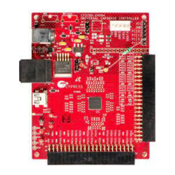
Unsolder the pull-up resistors, R57 and R58, which are connected to P1[5]–P1[7] on jumper J2, as shown in
2.
Short the resistor pads, R15 and R20, as shown in
CY8C24x94 device to the jumper J2.
Add Rb2 by connecting the 10-kΩ resistor between P0[5] and P1[5], as shown in
3.
4.
Connect header J1 of the CY3280-SLM daughter card to the 22x2_RA_Receptacle (connector P2) on the CY3280-24x94
UCC board.
5.
Place a jumper on header J1 to short the V
CapSense controller from the in-system serial programming (ISSP) connector.
6.
Place a jumper on header J4 to short the XRES and XRES/INT pins (pins 1 and 2) of the UCC board. This setting routes
the XRES pin of the CapSense controller to pin 3 of the ISSP connector J3; this is required only if you need to program
the device in the reset mode.
7.
Place a jumper on header J2 to short the GND and SHIELD pins (pins 2 and 3) of the CY3280-SLMboard. This setting
allows the board hatch pattern on the CY3280-SLM board to connect to the ground.
8.
Connect the MiniProg1/MiniProg3 to the ISSP header on J3 of the UCC board. This connection is required to program the
device with the generated hex file. This connection must be replaced with the CY3240-I2USB Bridge/MiniProg3 when the
CapSense data is read in the BCP software.
9.
Use the USB A to Mini-B cable to connect the other end of the MiniProg1/CY3240-I2USB Bridge/MiniProg3 to the PC.
Figure 5. Removing Pull-Up Resistors
Removed pull-up resistors
www.cypress.com
and 5-V pins of the UCC board. This setting allows you to power the
CC
Shorted pads
Document No. 001-66058 Rev.*E
Figure 5.
This setting connects the P1[5]–P1[7] pins from the
Figure
Figure 6. Connecting Rb2 between P1[5] and P0[5]
Rb2 connected between
P1[5] and P0[5]
Dynamically Switch CSD Bleed Resistor
Figure 5.
6.
5
