Ashly ne4800 Manual de instruções - Página 6
Procurar online ou descarregar pdf Manual de instruções para Hardware informático Ashly ne4800. Ashly ne4800 20 páginas. Network enabled dsp processor
Também para Ashly ne4800: Especificações (3 páginas), Manual de instruções (20 páginas), Manual (20 páginas)

Operating Manual - ne8800, ne4800, ne4400
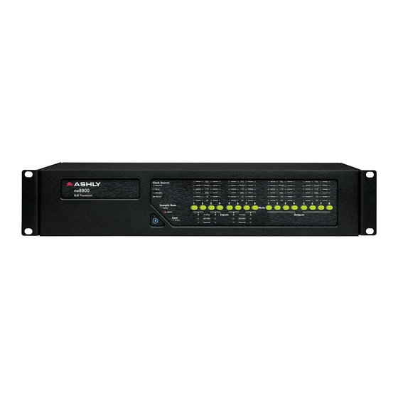
6. FRONT PANEL FEATURES
1. Power LED – Indicates the unit is turned on.
2. Clock Source – The Network clock, Word clock, AES3 clock, or Internal clock are indicated according to the master
clock source selected in the control software. The Network clock LED turns orange to indicate Net Matrix Mode.
3. Sample Rate – A 48KHz or 96KHz sampling rate can be selected from within software. A second function is also
indicated here when the firmware is reprogrammed with an updated file, as both sampling rate LEDs will light up for the dura-
tion of the file transfer (about two minutes).
4. Com LED – The Com LED indicates that data is being sent or received via the Ethernet control port. The Com LED
can also be made to flash on for two seconds to visually identify a physical unit from within the software.
5. Input Source – If more than one type of input is available for a given channel pair, an input source selection tab is
available in software. Here the user can select an input pair source as analog (line input), analog (mic preamp), AES3 input,
network audio, as well as set the input source selection to auto detect digital audio sources while automatically switching back
to analog input when no AES3 or network audio signals are present. Green LED color = "Selected", Red = "Not Valid", and
Off = "Not Being Used".
6. Input Level Meters – Input LED level meters reference the actual signal level at the A/D converter prior to the DSP
section. Levels displayed on the front panel are measured in dBFS (Decibels Full Scale), where 0dBFS is the maximum level
possible, thus are also true clipping indicators. The Threshold LED is used for dynamics functions configured in the DSP
Controls section of the software.
7. Input/Output Mute– This button is pressed to mute the input or output channel, and will additionally update that
channel's mute status as shown in software. Green means the channel is unmuted, while red means the channel is muted and
will not pass audio. For security, all front panel mute controls can be disabled from within software under <Device Options>,
then <Disable Front Panel Mutes>. If a mic input channel is set up for the push to talk function using logic I/O pins, that chan-
nel's mute button will illuminate orange to indicate its push to talk status, and turn green whenever the mic button is pressed.
8. Output Level Meters – Like the input meters, output meters reference 0dBFS, meaning 0dBFS is the true clipping
point, and are measured from the D/A converter point following the DSP section.
6
