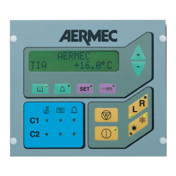
AERMEC NBW Manual de instruções de utilização - Página 9
Procurar online ou descarregar pdf Manual de instruções de utilização para Painel de controlo AERMEC NBW. AERMEC NBW 17 páginas. For chillers and heat pumps

NRA - NRC:
Parametro visualizzato
Descrizione
TIA
temperatura acqua ingresso evaporatore
TAE
temperatura aria esterna (non disponibile)
TUA C1
temperatura uscita acqua circuito 1
DELTAC1
differenziale temperatura acqua tra entrata e uscita
TL C1
temperatura freon liquido circuito 1
P.B. C1
pressione d'aspirazione circuito 1 (di serie nelle pompe di
calore, solo se è installato l'accessorio TP1 nei solo freddo)
P.A. C1
pressione di mandata circuito 1 (di serie nelle pompe di ca-
lore, solo se è installato l'accessorio TP2 nei solo freddo)
ATTESAC1
tempo di attesa minimo per il riavvio del circuito 1
SBRINAC1
tempo d'attesa che intercorre tra due sbrinamenti sul circui-
to 1 (pompa di calore)
TUA C2
temperatura uscita acqua circuito 2
DELTAC2
differenziale temperatura acqua tra entrata e uscita
TL C2
temperatura freon liquido circuito 2
P.B. C2
pressione d'aspirazione circuito 2 (di serie nelle pompe di
calore, solo se è installato l'accessorio TP1 nei solo freddo)
P.A. C2
pressione di mandata circuito 2 (di serie nelle pompe di ca-
lore, solo se è installato l'accessorio TP2 nei solo freddo)
ATTESAC2
tempo di attesa minimo per il riavvio del circuito 2
SBRINAC2
tempo d'attesa che intercorre tra due sbrinamenti sul circui-
to 2 (pompa di calore)
NRS - RS:
Parametro visualizzato
Descrizione
TIA
temperatura acqua ingresso evaporatore
TAE
temperatura aria esterna (non disponibile)
TUA
temperatura uscita acqua
DELTA
differenziale temperatura acqua tra entrata e uscita
TL C1
temperatura freon liquido circuito 1
TL C2
temperatura freon liquido circuito 2
P.B. C1
pressione d'aspirazione circuito 1 (solo se è installato
l'accessorio TP1)
P.A. C1
pressione di mandata circuito 1 (solo se è installato l'acces-
sorio TP2)
P.B. C2
pressione d'aspirazione circuito 2 (solo se è installato
l'accessorio TP1)
P.A. C2
pressione di mandata circuito 2 (solo se è installato l'acces-
sorio TP2)
ATTESAC1
tempo di attesa minimo per il riavvio del circuito 1
NRA - NRC:
Parameter
Description
TIA
evaporator water inlet temperature
TAE
ambient air temperature (not available)
TUA C1
outlet water temperature circuit 1
DELTAC1
inlet and outlet water temperature differential
TL C1
refrigerant liquid temperature circuit 1
P.B. C1
suction pressure circ. 1 (standard in heat pumps; only when
the TP1 accessory is installed in cooling only versions)
P.A. C1
delivery pressure circ. 1 (standard in heat pumps; only when
the TP2 accessory is installed in cooling only versions)
WAIT C1
min. stand-by time for re-start of circuit 1
DEFR. C1
time interval between two defrosting cycles on circuit 1
(heat pump)
TUA C2
outlet water temperature circuit 2
DELTAC2
inlet and outlet water temperature differential
TL C2
refrigerant liquid temperature circuit 2
P.B. C2
suction pressure circ. 2 (standard in heat pumps; only when
the TP1 accessory is installed in cooling only versions)
P.A. C2
delivery pressure circ. 2 (standard in heat pumps; only when
the TP2 accessory is installed in cooling only versions)
WAIT C2
min. stand-by time for re-start of circuit 2
DEFR. C2
time interval between two defrosting cycles on circuit 2
(heat pump)
NRS - RS:
Parameter
Description
TIA
evaporator water inlet temperature
TAE
ambient air temperature (not available)
TUA
outlet water temperature
DELTA
inlet and outlet water temperature differential
TL C1
refrigerant liquid temperature circuit 1
TL C2
refrigerant liquid temperature circuit 2
P.B. C1
suction pressure circ. 1 (only when the TP1 accessory is
installed)
P.A. C1
delivery pressure circ. 1 (only when the TP2 accessory is
installed)
P.B. C2
suction pressure circ. 2 (standard in heat pumps; only when
the TP1 accessory is installed in cooling only versions)
P.A. C2
delivery pressure circ. 2 (standard in heat pumps; only when
the TP2 accessory is installed in cooling only versions)
WAIT C1
min. stand-by time for re-start of circuit 1
9
