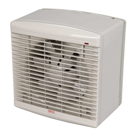
Domus Ventilation DX Series Руководство по установке и обслуживанию - Страница 5
Просмотреть онлайн или скачать pdf Руководство по установке и обслуживанию для Вентилятор Domus Ventilation DX Series. Domus Ventilation DX Series 7 страниц. Fan module 50hz/60hz
Также для Domus Ventilation DX Series: Руководство по установке и обслуживанию (8 страниц), Руководство по установке и обслуживанию (7 страниц)

Installation and Maintenance
DX Fan Module 50Hz/60Hz
4.5 Fitting Integral Sensors (Optional)
4.5 Fitting Integral Sensors (Optional)
4.5 Fitting Integral Sensors (Optional)
Note: Before following the pictorial sequence shown, first remove the
Note: Before following the pictorial sequence shown, first remove the
Note: Before following the pictorial sequence shown, first remove the
fans front cover grille (2 screws). Release the four main corner screws
fans front cover grille (2 screws). Release the four main corner screws
fans front cover grille (2 screws). Release the four main corner screws
and lift out the motor/fan plate assembly. Remove the electrical cover
and lift out the motor/fan plate assembly. Remove the electrical cover
and lift out the motor/fan plate assembly. Remove the electrical cover
plate opposite the sensor plate. Follow the pictorial sequence on this
plate opposite the sensor plate. Follow the pictorial sequence on this
plate opposite the sensor plate. Follow the pictorial sequence on this
page.
page.
page.
2
2
2
Remove the module plate.
Remove the module plate.
Remove the module plate.
4
4
4
Plug the connector into the required sensor module.
Plug the connector into the required sensor module.
Plug the connector into the required sensor module.
4.6 Typical Application
4.6 Typical Application
4.6 Typical Application
This shows an DX Fan Module being
This shows a DX Fan Module being
This shows an DX Fan Module being
retrofitted into an existing wall aperture.
retrofitted into an existing wall aperture.
retrofitted into an existing wall aperture.
The two internal wall battens are used to
The two internal wall battens are used to
The two internal wall battens are used to
support the fan and should be arranged
support the fan and should be arranged
support the fan and should be arranged
to match the fan fixing centres as listed
to match the fan fixing centres as listed
to match the fan fixing centres as listed
in the table.
in the table.
in the table.
Unit
Unit
Unit
X
X
X
DX6
DX6
DX6
237
237
237
DX9
DX9
DX9
310
310
310
DX12
DX12
DX12
390
390
390
LAB1346R May 2018
Y
Y
Y
Fan fixing slots. Arrange
Fan fixing slots. Arrange
Fan fixing slots. Arrange
support battens to suit.
support battens to suit.
support battens to suit.
8
8
8
8
8
8
8
8
8
1
1
1
1
1
1
Unscrew the module plate from motor plate assembly.
Unscrew the module plate from motor plate assembly.
Unscrew the module plate from motor plate assembly.
3
3
3
Lift out the sensor module wiring connector.
Lift out the sensor module wiring connector.
Lift out the sensor module wiring connector.
5
5
5
Screw the sensor module into position.
Screw the sensor module into position.
Screw the sensor module into position.
Wooden support
Wooden support
Battens
Battens
Existing wall
Existing wall
Existing wall
aperture
aperture
aperture
and outlet louvre
and outlet louvre
and outlet louvre
Fan fixing screws
Fan fixing screws
V E N T I L A T I O N
Wooden support
Battens
Fan Module
Fan Module
Fan Module
Internal
Internal
Internal
grille
grille
grille
Fan fixing screws
Page 5
