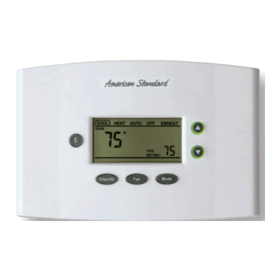
American Standard ACONT402AN32DA Руководство монтажника - Страница 3
Просмотреть онлайн или скачать pdf Руководство монтажника для Термостат American Standard ACONT402AN32DA. American Standard ACONT402AN32DA 18 страниц.

8. Match and connect control wires to proper terminals on the
connector block. (See the following wire diagrams).
9. Push any excess wire back into the wall and seal the hole
to prevent air leaks.
Note: Air leaks in the wall behind the control can cause
improper operation.
10.Check the operation of the business card drawer. Verify
that it slides in and out without binding.
11. Reinstall the control on its mounting base by aligning the
control at the top of the mounting base. Swing the control
downward and gently press the bottom of control into
position until latch button A engages. See Figure 1.
12.Turn ON power to the heating and cooling equipment.
$
Filter/OD
OT1
Outdoor Temp
OT2
Outdoor Temp
Y2
W3
R
Pub. No. 11-HD03D3-3
Figure 6
Fan
Mode
COMFORT CONTROL
TERMINAL BLOCK
Y/
W2
G
W1
Y1
Installer's Guide
SETUP
Enter INSTALLER Setup:
(See Table 3, step 1 - 49 for option details)
1.) Set System Mode to OFF
2.) Set Fan to AUTO
3.) Press and hold Mode and Up Arrow at the same time.
4.) SET-UP will appear on display. See Figure 6.
Enter USER Setup:
(See Table 3A, steps 50-62 for option details)
Press and hold Mode and Fan at the same time.
Note: Allow a minimum of 5 seconds after saving selections
(Step 99 - SA) for the control to write selections to memory.
If power is lost or removed prior to the 5 second elapsed
time, the selections may be lost and must be reentered. If
the SERVICE icon is flashing on the control LCD, press any
key and check / re-enter setup choices.
Keypad Navigation:
Use the Mode and Fan buttons to navigate forward and
backward through the configuration and Manual Test Mode
steps.
Press Mode to advance forward to the next step.
Note: Dual Fuel Applications.
system type is HP and the Indoor Heater Type is Gas or Oil
(Dual Fuel System) the JP1 jumper on the PCB must be cut.
Remote Indoor Sensor
Remote Indoor Sensor
O
B
BK
H1
When the
RS1
RS2
H2
3
