Ekinex EK-IE1-SEC-TP Инструкции по монтажу - Страница 2
Просмотреть онлайн или скачать pdf Инструкции по монтажу для Оборудование для звукозаписи Ekinex EK-IE1-SEC-TP. Ekinex EK-IE1-SEC-TP 5 страниц.

Connectors
• Bus connector for KNX (red / black)
• LAN RJ-45 socket
Environmental conditions
• Operating temperature: - 5 ... + 45 °C
• Non-operating ambient temp.: - 25 ... + 70 °C
• Relative humidity: 5 ... 93% not condensing
Switching and display elements
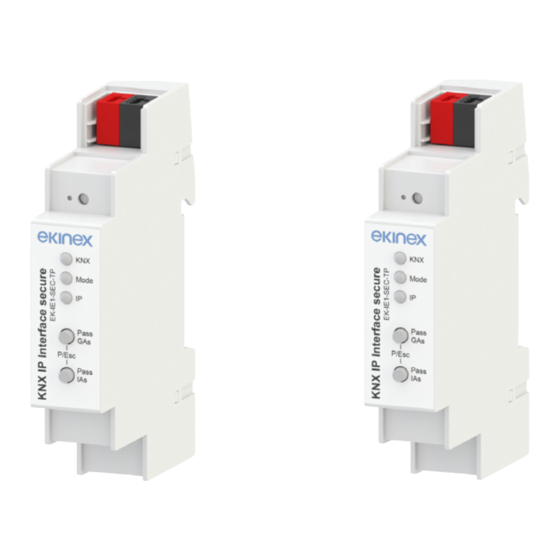
The devices are equipped with a programming pushbut-
ton and a programming LED, two operating buttons, three
LEDs for status indication, terminals for connecting the
KNX bus line and the Ethernet/LAN.
Switching elements
• Pushbutton (3) for switching between the normal and
programming operating mode. This operation can be
done by simultaneously pressing the pushbuttons (7)
and (8) as well;
• Pushbuttons (7), (8) to perform the following operation:
a) for EK-IE1-SEC-TP, they allow to choose each single con-
nection. Conn Up counts the connection numbers up and
Conn Dn down. The actually selected connection number is
indicated by flashing (1x...5x times) of the Mode LED (5);
b) for EK-IF1-SEC-TP, with the button Pass GAs the forwar-
ding of Group Addressed telegrams can be activated, while
the button Pass IAs activates the forwarding of Individually
Addressed telegrams.
2
4
6
9
EK-IE1-SEC-TP
1) KNX Bus connector
2) LED for Programming Mode (red)
3) Programming Mode button
4) KNX LED (multicolor)
5) Mode LED (multicolor)
6) IP LED (multicolor)
7) Connection Up button
8) Connection Down button
9) Ethernet/LAN connector
Display elements
• Red LED (2) for displaying the active operating mode of
the device (on = programming, off = normal operation)
• Multicolor KNX LED (4), that lights up green if the de-
vice is successfully powered by the KNX bus. The LED
indicates telegrams on the KNX bus by flickering. Com-
munication failures (e.g. repetitions of telegram or tele-
gram fragments) are indicated by a short change of the
LED color to red.
• Multicolor Mode LED (5):
• Multicolor IP LED (6), that lights up when an Ethernet
link is active. This LED is green if the device has valid
IP settings (IP address, Sub net and Gateway). With
invalid or nonexistent IP settings, or if the device has
not yet received the IP settings by a DHCP server, the
LED is red. The LED indicates IP telegrams by flicke-
ring green.
For detailed information on configuration options, refer to
the application manual of the device.
1
3
5
7
8
1) KNX Bus connector
2) LED for Programming Mode (red)
3) Programming Mode button
4) KNX LED (multicolor)
5) Mode LED (multicolor)
6) IP LED (multicolor)
7) Pass GAs (Group Addresses) button
8) Pass IAs (Individual Addresses) button
9) Ethernet/LAN connector
2
a) for EK-IE1-SEC-TP, it shows the actually selected connec-
tion number by flashing (1x...5x times). An available KNXnet/
IP Tunneling connection is indicated by a green light and a
used tunneling connection is indicated by an orange light.
b) for EK-IF1-SEC-TP, it shows the forwarding of Individual
and/or Group Adressed telegrams.
2
4
6
9
EK-IF1-SEC-TP
1
3
5
7
8
