Ekinex EK-EA2-TP Руководство - Страница 3
Просмотреть онлайн или скачать pdf Руководство для Блок управления Ekinex EK-EA2-TP. Ekinex EK-EA2-TP 4 страницы. 4-fold pushbutton

1
2
3
4
5
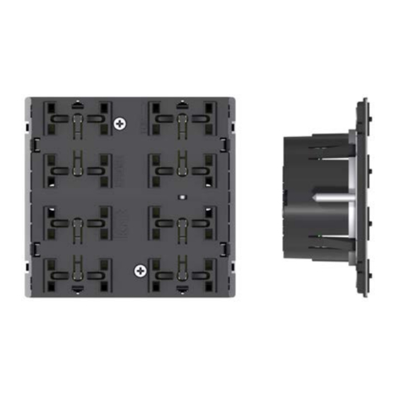
1) Programming LED
2) Programming pushbutton
3) Connection terminal block for KNX bus line
4) Seat for mounting the rocker (in the example: square rocker 40x40 mm)
5) Light guide for LED
Connection of the KNX bus line
The connection of the KNX bus line is made with the ter-
minal block (black/red) included in delivery and inserted
into the slot of the housing.
Characteristics of the KNX terminal block
• spring clamping of conductors
• 4 seats for conductors for each polarity
• terminal suitable for KNX bus cable with single-wire
conductors and diameter between 0.6 and 0.8 mm
• recommended wire stripping approx. 5 mm
• color codification: red = + (positive) bus conductor,
black = - (negative) bus conductor
!
Warning! In order to supply the KNX bus lines use
only KNX bus power supplies (e.g. ekinex EK-AB1-
TP or EK-AG1-TP). The use of other power supplies
can compromise the communication and damage
the devices connected to the bus.
+
Bus
KNX
-
!
Warning! The electrical connection of the device
can be carried out only by qualified personnel. The
incorrect installation may result in electric shock or
fire. Before making the electrical connections, make
sure the power supply has been turned off.
Configuration and commissioning
Configuration and commissioning of the device require
the use of the ETS
(Engineering Tool Software) program
®
V4 or later releases. These activities must be carried out
according to the design of the building automation system
done by a qualified planner.
i
Note. The configuration and commissioning of KNX
devices require specialized skills. To acquire these
skills, you should attend the workshops at KNX cer-
tified training centers.
Configuration
For the configuration of the device parameters the corre-
sponding application program or the whole ekinex® pro-
duct database must be loaded in the ETS program. For
detailed information on configuration options, refer to the
application manual of the device available on the website
www.ekinex.com
Product
Application program
code
(## = release)
EK-EA2-TP
APEKEA2TP##.knxprod
Commissioning
For commissioning the device the following activities are
required:
• make the electrical connections as described above;
• turn on the bus power supply;
• switch the device operation to the programming mode
by pressing the programming pushbutton located on
the rear side of the housing. In this mode of operation,
the programming LED is turned on;
• download into the device the physical address and the
configuration with the ETS
At the end of the download the operation of the device
automatically returns to normal mode; in this mode the
programming LED is turned off. Now the bus device is
programmed and ready for use.
Dimensions [mm]
82
3
Communica-
Group
tion objects
adresses
(nr. max)
(nr. max)
156
254
program.
®
35
29
6
