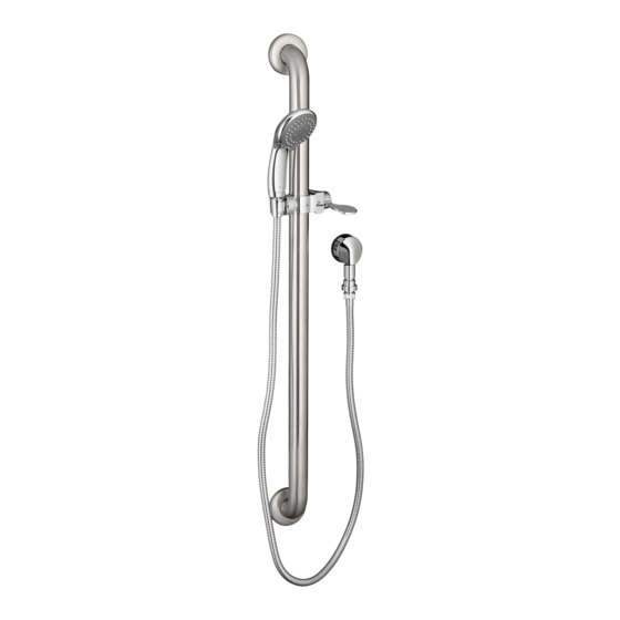
American Standard 1662SG.223 Руководство по установке - Страница 4
Просмотреть онлайн или скачать pdf Руководство по установке для Кухня и аксессуары; светильники для ванной American Standard 1662SG.223. American Standard 1662SG.223 6 страниц. Commercial shower system kits: 1.5 gpm & 2.5 gpm

8
INSTALLATION INSTRUCTIONS
The SLIDE BAR (1) works best when secured to the wall studs or cross brace using WOOD SCREWS. If mounting
into the studs is not possible, use appropriate wall fasteners provided to secure the installation.
Mark a vertical center line in the location you wish to install the SLIDE BAR (1). NOTE: The height from the finished
floor is optional. See rough-in drawing for suggested dimensions.
Determine desired height from the finished floor to the lower support and mark a horizontal center line. Slide the two
WALL ESCUTCHEONS (5) away from the MOUNTING FLANGES (3). Position the SLIDE BAR (1) as shown in Fig. A and
mark the location of the six mounting holes to be drilled. Fig. A. Using a #10 masonry drill, drill six mounting holes
1-1/4" max. deep. Fig. B.
Install the six ANCHORS (2) provided into the mounting holes. Use a hammer to lightly tap ANCHORS (2) into place.
Make sure they are installed flush against the finished wall. Fig. B.
Align and place the SLIDE BAR MOUNTING FLANGES (3) over the installed ANCHORS (2). Secure the SLIDE BAR (1)
to the wall with the SCREWS (4) provided. Fig. B.
Push WALL ESCUTCHEONS (5) against finished wall. Rotate WALL ESCUTCHEONS (5) clockwise to lock into
position. Fig. C.
Make sure larger diameter side of SPRAY HOLDER (6) is facing upward. If not rotate SPRAY HOLDER (6) 180 dergees.
Rotate the LEVER HANDLE (7) to the unlocked position. Push the SPRAY HOLDER (6) side onto the GRAB BAR (1).
Push the LEVER HANDLE SIDE (7) over the SPRAY HOLDER ARMS (8) until the two snap togerther.
Check operation of SLIDE BAR (1) by rotating HOLDER LEVER (7) and moving HAND SHOWER HOLDER (9) up and down.
Rotate LEVER HANDLE (7) back to lock HAND SHOWER HOLDER (6). Fig. B.
Fig. A
C/L
914mm
(36")
1
OPTIONAL TO FINISHED FLOOR
FINISHED
FLOOR
CARE INSTRUCTIONS:
DO: SIMPLY RINSE THE PRODUCT CLEAN WITH CLEAR WATER. DRY WITH A SOFT COTTON FLANNEL CLOTH.
DO NOT: DO NOT CLEAN THE PRODUCT WITH SOAPS, ACID, POLISH, ABRASIVES, HARSH CLEANERS, OR A CLOTH
WITH A COARSE SURFACE.
Fig. B
3
4
5
VERTICAL
CENTER LINE
1
LEVEL
5
USUALLY BETWEEN
915mm
TO
1525mm
(36")
(60")
2
DRILLED
MOUNTING
HOLES
LARGE
DIAMETER UP
6
Fig. C
1
8
LOCK
M965668 Rev. 1.3 (1/17)
ROTATE
CLOCKWISE
TO LOCK
5
UNLOCK
7
