AMERITRON AL-811HY Руководство - Страница 6
Просмотреть онлайн или скачать pdf Руководство для Усилитель AMERITRON AL-811HY. AMERITRON AL-811HY 13 страниц.
Также для AMERITRON AL-811HY: Инструкция по распаковке Руководство (11 страниц)

CW PROCEDURE
Follow the instructions in numerical order. If the various meter
readings are different than those indicated in the instructions,
check the connections from the exciter to the amplifier and make
sure they are correct. Consult the manual for the exciter, if
necessary. Be sure the transformer is correctly wired for your
line voltage.
See the
instructions on page 4 for wiring details.
1.
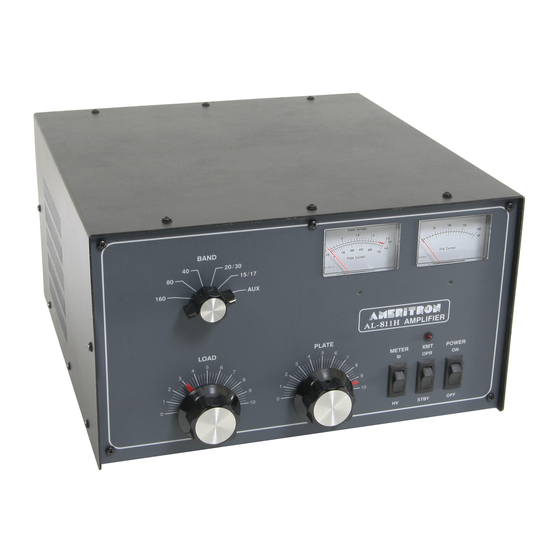
Set the AL-811H front panel switches as follows:
POWER/OFF-ON to OFF
XMT/OPR-STBY to STBY
METER/Ip-HV to HV
2.
Plug the line cord into a proper voltage outlet.
3.
Set the POWER switch to the ON position. The meter
lamps should light and the fan should start. Read the 2000
volt scale on the multimeter. It should indicate 1700 volts
nominally and no more than 1800 volts.
4.
With the amplifier XTM switch still on STBY, tune the
exciter into the normal 50 ohm load according to the
manufacturer's instructions. Turn the exciter drive fully
down after tuning.
5.
Place the amplifier bandswitch on the same band as the
exciter, the PLATE control in the dial range for the band
selected, and the LOAD control as indicated:
MHz
Plate
Load
1.80
1 1/2
6 1/2
1.90
3
7 1/2
3.5
5
2
3.7
6
3
4.0
6 1/2
5 1/2
7.0
8
3
7.3
8
3 1/2
POWER CONNECTIONS
MHz
Plate
Load
10.1
7 1/2
14.0
9
18.1
9
2 1/2
21.0
9 1/2
24.9
9 1/2
4 1/2
28.5
9 1/2
TUNE-UP
6.
With the exciter drive still at zero, place the METER/HV-
Ip switch in the Ip position. Observe the 750mA scale. It
should read zero. Place the XMT/STBY-OPR switch in
the OPR position.
7.
Key the exciter (no drive). The Transmit (XMT) LED
should light. Observe the plate current on the 750mA scale.
It should be 125mA.
NOTE: The no drive current will vary up to 25% due to
8.
Apply only enough drive to indicate a grid current of
100mA, or an Ip of no more than 450mA.
PLATE control for maximum output power. It is normal
for the plate current to dip at this point. If the grid current
goes over 200mA, reduce the drive at once. Unkey the
exciter.
9.
Observe the output on an external RF wattmeter. Increase
the drive until full exciter power (never to exceed 80 watts)
or 200mA of grid current, is achieved. Quickly adjust the
PLATE and LOAD controls for maximum output power.
10. Reduce the drive until the desired output levels are
obtained.
NOTE: Rotating the LOAD control clockwise reduces grid
0
3
4
5
component and line voltage tolerances.
current for a given amount of drive. If the LOAD
control is set at too low a numerical setting, a severe
stress on tank components may occur. The PLATE
control should always be peaked for maximum grid
current or output power. Do not exceed 750mA of
plate current during tune-up.
Tune the
6
