DoorHan PCB-SW Руководство по программированию - Страница 12
Просмотреть онлайн или скачать pdf Руководство по программированию для Панель управления DoorHan PCB-SW. DoorHan PCB-SW 20 страниц. Control board
Также для DoorHan PCB-SW: Руководство по программированию (20 страниц)
Type
Colour
Control board power
Red
supply
Motor power supply,
gate leaf No. 1
Grey
Motor power supply,
gate leaf No. 2
Signal lamp
Yellow
Control devices
Green
Safety devices
Orange
Control device
Orange
Accessories
White
End position reader
Blue
Antenna
Green
12
Connector
Terminal
PE
X1
N
Connecting the board to 220 V AC power supply
L
M-N
X2
M-L1
Connecting the power supply of the electric motor of the gate leaf No. 1
M-L2
M-N
X3
M-L1
Connecting the power supply of the electric motor of the gate leaf No. 2
M-L2
X4
AC_Lamp Connection of the signal lamp of AC voltage 220V
SBS
X5
Step-by-step control or opening contact (depends on the operation logic)
GND
Ped.
X6
Step-by-step control or closing contact (depends on the operation logic)
GND
Ph.Pwr+
Connecting the power supply of photocells 24 V
Ph.Pwr-
Connection of open direction photocells (NC). Response of the devices results in im-
mediate stop of the door. If the safety devices respond when the door is closed then
Ph.Op
it will prevent door opening. When using several devices connect their NC contacts
X7
in series
Connection of close direction photocells (NC). Response of the devices results in im-
mediate stop and reverse movement of the door to the full open position. If the safety
Ph.Cl
devices respond when the door is open then it will prevent door closing. When using
several devices connect their NC contacts in series
GND
Common contact for PH_OP and PH_CL
Stop
X8
Opening of these terminals generates STOP command
GND
Power+
X9
Connection of the power supply of additional accessories 24 V (max 500 mA)
Power-
OUT
X10
Electric lock connection
S.Lock
Sw.Cl.1
Connection of the close direction end switch of the gate leaf No. 1
X11
Sw.Op.1
Connection of the open direction end switch of the gate leaf No. 1
GND
Common contact for Sw.Op. and Sw.Cl.
Sw.Cl.2
Connection of the close direction end switch of the gate leaf No. 2
X12
Sw.Op.2
Connection of the open direction end switch of the gate leaf No. 2
GND
Common contact for Sw.Op. and Sw.Cl.
Antenna
X13
Connection of the external antenna of the remote control receiver
GND
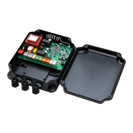
ELECTRICAL CONNECTIONS
Connections