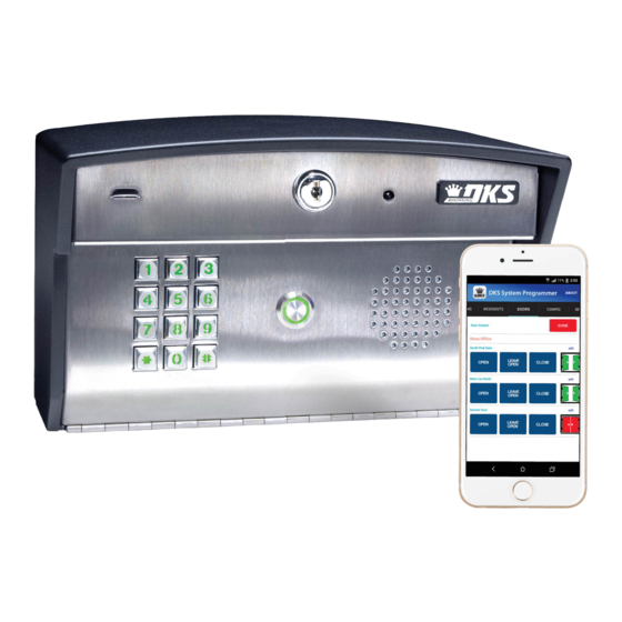
DoorKing 2112 Руководство по установке и эксплуатации - Страница 7
Просмотреть онлайн или скачать pdf Руководство по установке и эксплуатации для Системы управления DoorKing 2112. DoorKing 2112 18 страниц. Internet/cellular programmable video telephone/access control system

General Information
•
Prior to beginning the installation of the telephone entry system, we suggest that you become familiar with the instructions, illustrations, and wiring
guidelines in this manual. This will help insure that you installation is performed in an efficient and professional manner.
•
The proper installation of the telephone entry panel is an extremely important and integral part of the overall access control system. Check all local
building ordinances and building codes prior to installing this system. Be sure your installation is in compliance with local codes.
•
When used to control a door or pedestrian gate, try to locate the telephone entry system as near as possible to the entry point. The unit should be
mounted on a rigid wall to prevent excessive shock and vibration from closing doors or gates. Continuous vibration and shock from slamming doors
or spring-loaded pedestrian gates will damage the circuit board. Under no circumstances should the unit be mounted directly to a moving door or gate.
•
ADA mounting requirements for door control (Ref: ICC/ANSI A117.1-2009). The requirements below apply ONLY when the telephone entry system is
being used to control entry through A PUBLIC DOOR ONLY. If this system is used to control entry through a vehicular gate or private entrance, the
dimensions noted below do not apply.
1.
Unobstructed Forward Reach.
ground space allows only a forward approach to an object
and is unobstructed, mounting height shall be a minimum
of 15 inches (381 mm), and a maximum of
48 inches (1.22 m), above the floor or
ground to the operable controls.
2.
OBSTRUCTED HIGH Forward Reach.
reach is over an obstruction, reach and clearances shall
be as shown. NOTE: If the height of a control is 48"
maximum, then the length of the obstruction
must be 20" or less. If the height of a control
is 44" maximum, then the length of the
obstruction may be increased to 25" or less.
3.
Unobstructed Side Reach.
space allows a parallel approach to an object and the side
reach is unobstructed, and the edge of the clear floor space
is 10 inches (255 mm) maximum from the object, mounting
height shall be a minimum of 15 inches (380 mm), and a
maximum of 48 inches (1.22 m), above the floor
or ground to the operable controls.
4.
OBSTRUCTED HIGH Side Reach.
an obstruction 10 inches or less, mounting height shall
be a maximum of 48 inches (1.21 m) above the floor or
ground to the operable controls. If the side reach
is over an obstruction greater than 10 inches,
but less than 24 inches, mounting height shall
be a maximum of 46 inches (1.17 m) above the
floor or ground to the operable controls.
•
When used to control a vehicular gate with an automatic gate operator, the telephone entry system must be mounted a minimum of six (6) feet
away from the gate and gate operator, or in such a way that a person cannot operate the entry system and/or touch the gate or gate operator at
the same time.
•
Be sure that the system is installed so that it is not directly in the traffic lane. Goose neck mounting post and kiosks work well for these type systems.
When planning where to locate the system, take into consideration traffic lane layouts, turn around lanes for rejected access, conduit runs, power
availability, etc.
•
Environmental factors must also be taken into account. Surface mount units are designed for direct outdoor installations, however it is preferable to
protect them from direct exposure to driven rain or snow whenever possible. Flush mount units must be protected from direct exposure to the
elements.
•
This telephone entry system contains a number of static sensitive components that can be damaged or destroyed by static discharges during
installation or use. Discharge any static prior to removing the circuit board from the lobby panel by touching a proper ground device.
•
Instruct the end user to read and follow these instructions. Instruct the end user to never let children play with or operate any access control
device. This Owner's Manual is the property of the end user and must be left with them when installation is complete.
2112-065-G-12-21
Where a clear floor or
Minimum
Height
If the high forward
Maximum
Height
Where a clear floor or ground
Minimum
Height
If the side reach is over
Maximum
48"
Height
15"
48"
20" or Less
15"
10" Maximum Length of
Clear Floor Space
Maximum
34"
10" or Less
Maximum
48"
Height
Maximum
44"
Height
25" or Less
Maximum
48"
Height
Maximum Length of
10"
Clear Floor Space
46"
Height
34"
Less than 24"
Greater than 10"
3
