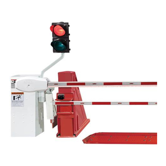
DoorKing 1620 Series Руководство по установке - Страница 8
Просмотреть онлайн или скачать pdf Руководство по установке для Автоматические барьеры DoorKing 1620 Series. DoorKing 1620 Series 16 страниц. Lane barrier
Также для DoorKing 1620 Series: Руководство по установке (20 страниц)

Entry Lane Only In-Ground Loop Options
Before attempting to connect any wiring to the operator, be sure that the
circuit breaker in the electrical panel is in the OFF position. Permanent wiring
must be installed to the operator as required by local electrical codes. It is
recommended that a licensed electrical contractor perform this work.
Loop detector wiring shown is for DoorKing model 9409 Dual Channel
plug-In loop detector only.
If using other loop detectors refer to their Loop Information Manual for
installation instructions, loops/preformed loops and wiring diagrams.
All inputs to the main terminal are NORMALLY OPEN.
Typical DIP-Switch Settings
OFF
OFF
OFF
Switch 4 is ON.
OFF
OFF
Switch 7 is OFF (Timer). The arm
will rotate down after the vehicle
OFF
clears the down loop.
SW 1
A
See timer note below.
OFF
OFF
OFF
OFF
Switch 5 is ON. The lowering arm
OFF
will instantly reverse when photo
sensor gets blocked.
OFF
OFF
SW 2
Arming Loop Note: The arming loop only allows the access control device to function when a vehicle is on the
loop, otherwise it will not function. This prevents pedestrians from gaining access through the vehicular gate.
Timer Note: The timer can be used with a down loop. When timer is ON with a down loop, it will start countdown
when the arm has fully raised. Activation of the down loop will cancel timer countdown. Useful when an access
control device OR ticket spitter has been activated but vehicle does not move forward to activate the down loop.
The arm will remain UP. Timer will time out and lower the arm without the down loop being activated.
1620-065-G-8-20
UP
LOOP
NO
Com
Down
Loop
Port
DOWN
LOOP
9409
Dual Channel
Main Terminal
1 2 3 4 5
If the ARMING LOOP is
not used, then a single
channel loop detector
can be used (9410) in the down loop port.
Connect the down loop to loop 1 on this
detector. Connect the access control device
directly to main terminal 6 and 14.
DoorKing offers a free "Loop and
Loop-Detectors Information
Manual" PDF located at
DoorKing's web site for more
information. www.doorking.com
TIME
DELAY
DIP
SW 1
A
Switches
1601-010
POWER
SW 2
REVERSE
SENSITIVITY
Photo
Sensor
NC NO
See page 8.
6
7 8
9
10 11 12 13
14
NO
5
Type of wiring to be used on ALL external devices:
A) Type CL2, CL2P, CL2R, or CL2X.
B) Other cable with equivalent or better electrical,
mechanical, and flammability ratings.
Down Loop
1 Ft. Minimum Distance
N O T A W A L K W AY
Arming Loop
for Access Control Device
Com
(Optional)
OR
Access
Ticket Eject Loop
Control
for Ticket Spitter (Required)
Device
OR
Ticket
Spitter
