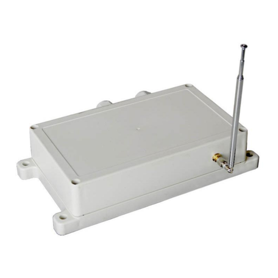
Flying Industry Development S4PXW-DC24-ANT3 Краткое руководство
Просмотреть онлайн или скачать pdf Краткое руководство для Приемник Flying Industry Development S4PXW-DC24-ANT3. Flying Industry Development S4PXW-DC24-ANT3 4 страницы. 5000 meters rf wireless receiver

5000 Meters RF Wireless Receiver (0020670)
Feature:
Wireless control, easy to install.
Waterproof case with waterproof connectors.
High power, each output can work at maximum 30A current.
Super long range, with a transmitter to form a complete set, the working distance can reach 5000m in an open ground.
Feedback function: Can let the user know whether the receiver is been successfully triggered or operated by the transmitter in such a long distance.
Two ways working mode: When the receiver is been successfully triggered by the transmitter, it will immediately transmit a feedback signal to the
transmitter, and the transmitter will send out a buzzing sound to inform you that the receiver has been successfully triggered.
America imported chips, which can ensure reliability and assure the high quality of the products.
DC power output, can be used in home automation, such as security system, remote control lights, motors, doors / locks / windows / blinds / cars, and
various equipment.
It also can be used in agriculture and industry automation, such as long range and high power remote control devices.
Wireless remote control products on land, water and air, especially in a long distance, such as farm, pasture, offshore unmanned operation, field call,
remote security alarm, unmanned aerial vehicle, etc.
You can turn on/off the receiver with transmitter (remote control) from any place within a reliable distance; the wireless RF signal can pass through
walls, floors and doors.
With characteristics of reverse power protection and over current protection
Reliable control: The transmitter (Encoding) and the receiver (Decoding) use the custom code.
One/several transmitters can control one/several receivers simultaneously.
You can use two or more units in the same place.
External Telescopic Antenna:
Length of external telescopic antenna: 108mm / 445mm (stretch)
External telescopic antenna use SMA connector.
If you stretches the external telescopic antenna, it can have a further working range, which is twice as much as it used to be.
Weight of external telescopic antenna : 16.5g
Receiver Parameters:
Model No. S4PXW-DC06-ANT3 / S4PXW-DC09-ANT3 / S4PXW-DC12-ANT3 / S4PXW-DC24-ANT3
Power Supply (Operating Voltage): DC6V (S4PXW-DC06-ANT3), DC9V±1V (S4PXW-DC09-ANT3), DC12V±1V (S4PXW-DC12-ANT3), DC24V±2V
(S4PXW-DC24-ANT3)
Output: DC6V (S4PXW-DC06-ANT3), DC9V±1V (S4PXW-DC09-ANT3), DC12V±1V (S4PXW-DC12-ANT3), DC24V±2V (S4PXW-DC24-ANT3)
Working Frequency: 433.92MHz
Channel: 4CH
Control Modes: Toggle, Momentary, Latched
Maximum Working Current: 30A / each channel
PCB size: 170mm x 109mm x 18mm
Case size:200mm x 120mm x 53mm
Work with custom code transmitters.
Usage (with the transmitter CC-4):
You can use this 4 channel receiver to control 4 DC equipments. If the power supply of those equipments is DC 12V, you should choose the receiver
with same DC 12V version; and if the power supply of those equipments is DC 24V, you should choose the receiver with same DC 24V version.
If you want to control four DC 12V lamps, do as following:
Connect DC 12V power to terminals "+" and "-", and connect lamp 1 to terminals "+" and "-" of OUT1, connect lamp 2 to terminals "+" and "-" of OUT2,
connect lamp 3 to terminals "+" and "-" of OUT3, connect lamp 4 to terminals "+" and "-" of OUT4 .
Setting different control modes: (We have set the receiver as Toggle control mode before delivery. If you want to use other control modes, do as
following operation):
Setting control mode Toggle (with transmitter CC-4): Move the first bit of the dip switch to the terminal "on" .
Control mode Toggle: Press -> On; Press again -> Off.
Press button A of the transmitter: Terminals OUT1 output DC power.
Press button A again: Terminals OUT1 stop outputting.
Press button B of the transmitter: Terminals OUT2 output DC power.
Press button B again: Terminals OUT2 stop outputting.
Press button C of the transmitter: Terminals OUT3 output DC power.
Press button C again: Terminals OUT3 stop outputting.
Press button D of the transmitter: Terminals OUT4 output DC power.
Press button D again: Terminals OUT4 stop outputting.
Setting control mode Momentary (with transmitter CC-4): Move the first and the second bits of the dip switch to the terminal "on".
Control mode Momentary: Press and hold -> On; Release -> Off.
Press and hold button A of the transmitter: Terminals OUT1 output DC power.
Release button A of the transmitter: Terminals OUT1 stop outputting.
Press and hold button B of the transmitter: Terminals OUT2 output DC power.
Release button B of the transmitter : Terminals OUT2 stop outputting.
Press and hold button C of the transmitter: Terminals OUT3 output DC power.
SHENZHEN GUIYUAN INDUSTRY DEVELOPMENT CO.,LTD
Http://www.carymart.com
E-Mail: [email protected]
