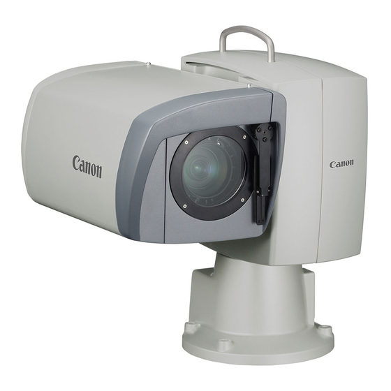
Canon BU-51H Краткое руководство по эксплуатации - Страница 5
Просмотреть онлайн или скачать pdf Краткое руководство по эксплуатации для Объектив камеры Canon BU-51H. Canon BU-51H 8 страниц. Canon remote control pan-tilt system
Также для Canon BU-51H: Карманное руководство (22 страниц), Руководство пользователя (2 страниц), Карманное руководство (22 страниц), Руководство по дистанционному управлению (2 страниц), Брошюра и технические характеристики (4 страниц)

Canon BU Series PTZ Camera Systems
Step 4: BU-47H Camera System ONLY
Carefully loosen the four hex screws from the housing on the back of the pan/tilt base. 18 inches of flexible plastic
conduit is supplied with the camera, along with a coupler connected to the weatherproof housing on the back of the
camera. The opening in the back of the housing is 1.67 inches in diameter if it is determined that another type of
weatherproof conduit is required for the specific installation.
Connect the positive (+) and negative (-) connections to the screw terminals on the camera. Connect the BNC
cable for HD-SDI to the SDI output connector. If sync and/or composite video is required for the installation run
additional coax cables to the Sync and VBS ports on the back of the camera.
Next, remove the 12-pin connector that was supplied with the BU-47H by grasping the collar and pulling outward.
Locate the 12-pin to RJ-45 adapter cable (see the diagram below), and connect the 12-pin connector to the camera.
Plug in the Cat. 5e cable that was run to the camera and connect the RJ-45 connector to the other end of the 12-pin
cable. Note: the RS-232 to RS-422 converter should be placed by the Vaddio joystick controller (see Figure 2).
NOTE: Be sure to turn on the power switch (labeled "POWER SW" in the diagram below) on the pan/tilt head,
before putting the housing back on the pan/tilt base.
Step 4: BU-51H
Connect the RJ-45 to DB-9 adapter to the CONTROL port on the back of the pan/tilt head. Connect the power and
control cables that were supplied with the BU-51H camera into the appropriate ports on the camera and pan/tilt
head. Refer to the Canon manual for additional details on cable placement. Connect the AC cord to the back of the
pan/tilt head.
Step 5:
After completing the installation of the camera, connect the Cat. 5e cabling to the back of the Vaddio joystick
controller. Follow the programming instructions provided with the Vaddio joystick controller in order for it to
recognize the Canon BU series camera.
Canon BU-Series PTZ Camera Installation and User Guide 341-909 Rev. C
BU-47H
Camera
Cable
Enlarged
BU-51H
Camera
Connect to Control
Connector
Cat. 5e cable from
ProductionVIEW
Control Port
Connect Control
Adapter to BU-51
Control Port
Page 5 of 8
