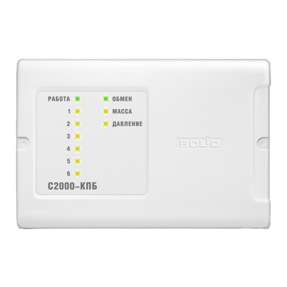
bolid S2000-KPB Руководство по эксплуатации - Страница 9
Просмотреть онлайн или скачать pdf Руководство по эксплуатации для Блок управления bolid S2000-KPB. bolid S2000-KPB 14 страниц. Executive module
Также для bolid S2000-KPB: Руководство по эксплуатации (17 страниц)

to alarm loops
An example of an alarm
loop with a normally
open detector
4.7kOhm
2 kOhm
An example of an alarm
loop with a normally
closed detector
3.3 kOhm
4.7 kOhm
to the power supply 1
+12 V...+24 V
0 V
to the power supply 2
+12 V...+24 V
0 V
to the console,
S2000-ASPT, or PC
RS-485
Notes:
1. The type of executive devices to be connected to the outputs is to be defined by user and can
differ from the shown devices.
2. The load connection modules should be installed in proximity to the executive devices.
3. If an output is not in use, a 1kOhm - 0.5 W resistor can be used instead of the load
connection module.
4. Normally open and normally closed detectors can be combined and brought into the same
circuit if only a single detector can be in activated status.
S2000-KPB
XT2.3
5
loop 1+
MASS
6
loop 1-
XT2.4
7
loop 2+
PRES
8
loop 2-
XT2.1
1
+Umain
2
0 V
READY
XT2.2
3
+Uback
4
0 V
XT2.5
9
RS-485A
COM
10
RS-485B
Figure 3. S2000-KPB Wiring Diagram
XT1.1
Out.1 -
1
«1»
Out.1 +
2
XT1.2
Out.2 -
3
«2»
Out.2 +
4
XT1.3
Out.3 -
5
«3»
Out.3 +
6
XT1.4
Out.4 -
7
«4»
Out.4 +
8
XT1.5
Out.5 -
9
«5»
Out.5 +
10
XT1.6
Out.6 -
11
«6»
Out.6 +
12
2
3
ч
ч
Lamp
LCM
к
б
1
4
2
3
ч
ч
Siren
LCM
к
б
1
4
2
3
ч
ч
Lock
LCM
к
б
1
4
2
3
ч
ч
Discharge
LCM
Circuit
к
б
1
4
2
3
ч
ч
Discharge
LCM
Circuit
к
б
1
4
2
3
ч
ч
Discharge
LCM
Circuit
к
б
1
4
Load Connection Module
(LCM)
black
black
2
3
red
while
1
4
9
