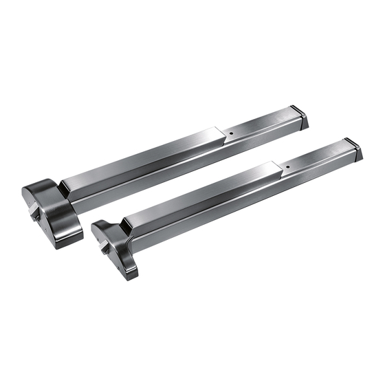
Dormakaba 9700DE Руководство по установке - Страница 5
Просмотреть онлайн или скачать pdf Руководство по установке для По замкам Dormakaba 9700DE. Dormakaba 9700DE 10 страниц. Delayed egress exit device

dormakaba 9000 Delayed Egress Exit Device Installation
Instructions
1.5
Basic wire connection
Specific project or custom wiring diagrams available on re-
quest, consult the dormakaba techinical service department.
"Product intended for indoor use."
NOTE: Always disconnect power prior to making any
connections or service.
It is recommended that the 120VAC power be supplied
from an Uninterrupted Power Supply (UPS) to ensure
proper operation during a power failure.
Always observe proper static discharge grounding pro-
cedure's when installing or servicing the DE device.
Wires that interconnect (+) 24Vdc, (-) 24Vdc, authorized
egress/auto reset, and all other secondary connections must
be located within the same room as the panic hardware per
UL294.
For ULC installations: Some "Authorities Having Juris-
diction" also require an illumination level of 100' feet at
the door, to be provided by the emergency power supply
system.
DORMA ES100
Maximum Wire Length From Power Supply To
Device & Back To Supply In Feet x Wire Gage/Size
WIRE 18AWG
FEET
* For 24VDC inputs only (red & black wires).
Note: Wire run is from supply to device
and back to the supply.
Exit Device
REPLACE WITH 3AG 3/4 AMP
SLO-BLOW TYPE FUSE ONLY
Minimum 18 AWG
wire recommended for
24VDC inputs (red &
black) leads.
DORMA ES105
(Power transfer)
"required"
16AWG
14AWG
12AWG
25
50
75
100
95011817 (1135-88) IDE-20
dormakaba MODEL ES100
24 VOLT DC POWER SUPPLY
(AD100 220V Version Optional)
PUSH
FUSE
TO RESET
CIRCUIT
BREAKER
3.0 AMP
3/4 AMP
24VDC
120VAC
ZONE 1
ZONE 2
OUTPUT
OUTPUT
CONTROL
CONTROL
TERMINALS
TERMINALS
SWITCH
SWITCH
24VDC
24VDC
(+)
(+)
(+)
(+)
(-)
(IN)
(-)
(IN)
1
2
3
4
5
6
7
8
Green Ground
Screw Located
On Chassis
CAUTION:
TURN OFF 120VAC POWER PRIOR TO MAKING ANY CONNECTIONS TO TERMINALS
(NEUTRAL)
WHITE
120 VAC
BLACK
(HOT)
POWER LINE
GREEN
(GROUND)
(1.0 AMP MAX.)
Control Inputs
(12) Wire primary connection
bundle 22" in length.
BLACK: (-) 24VDC IN
RED: (+) 24VDC IN
WHITE: AUTHORIZED EGRESS/AUTO RESET
ORANGE: BYPASS/RE-ARM
GREY: DPS N/C
VIOLET: ALARM RELAY COMMON
GREEN: RED OUTPUT EMITTER
BROWN: RED OUTPUT COLLECTOR
BLUE: GREEN OUTPUT EMITTER
YELLOW: GREEN OUTPUT COLLECTOR
PINK: ALARM RELAY N/C
TAN: ALARM RELAY N/O
Basic wire connection
NO
CONNECTION
9
10
11
12
From UPS
Power Source
Monitoring
Outputs
(See Page 6 for typical
wiring of control inputs
Grey
and monitoring outputs.)
DPS
Black
Note: "The fire alarm contact is to be
used as a supplementary feature and
not intended to replace required fire
alarm appliances".
BLACK: NOT USED
BLUE: 24VDC for acc.
GREEN: FIRE ALARM CONTACT
BROWN: 24VDC for acc.
VIOLET: CHECK EXIT
RED: TIED TOGETHER WITH
OTHER DOOR ON PAIRS
(6) Wire secondary connection
bundle 22" in length.
01-2020
5
