COM-power corporation CLCE-400 Руководство по эксплуатации - Страница 9
Просмотреть онлайн или скачать pdf Руководство по эксплуатации для Измерительные приборы COM-power corporation CLCE-400. COM-power corporation CLCE-400 18 страниц. Rf current probe and calibration fixture
Page 9 of 18
INSTRUCTION MANUAL
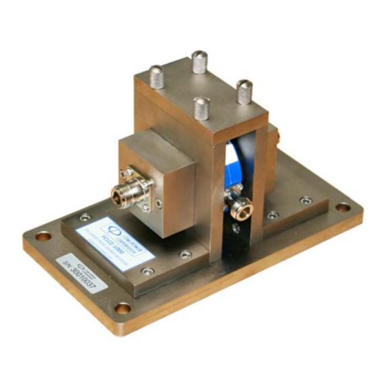
Fixture Opening
The CLCE-400 is installed within this opening so that the center conductor rod of the fixture
passes through the approximate center of the probe aperture.
Center Conductor Rod
This is the fixture's center conductor.
Calibration Fixture Coaxial Ports
These are female N-type coaxial connectors providing input/output connections to the
fixture.
Thumb Screws for Removable Top Plate
These (4) screws secure the fixture's removable top plate to the assembly.
Removable Top Plate of Fixture
In order to install/remove the clamp into/from the calibration fixture, the top plate must be
removed by removing the four (4) thumb screws. The top cover and thumb screws must be
replaced prior to the performance of tests.
Teflon Spacers
These spacers center the clamp within the fixture; thereby aligning the center conductor
through the center of the probe window.
- P R O D U C T I N F O R M A T I O N
S E C T I O N 3
Rev0305