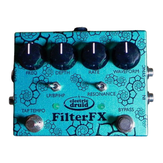
Electric Druid FilterFX Project Руководство по строительству - Страница 5
Просмотреть онлайн или скачать pdf Руководство по строительству для Музыкальная педаль Electric Druid FilterFX Project. Electric Druid FilterFX Project 11 страниц.

Electric Druid FilterFX Construction Guide
Vactrols
There are two Xvive VTL5C3 optocouplers ("vactrols" or "optos"). They're the massive things in
the middle and they're clearly marked on the silkscreen, so you can't miss 'em! Make sure you get
them the right way around. The end of the vactrol marked LED has a + symbol, and the legs are
close together on a 0.1"/2.5mm spacing. The end of the vactrol marked LDR or CELL has a wider
spacing of 0.2"/5mm.
Second cup of tea and Power Test
Drilling the enclosure
The PCB is designed to be mounted in landscape format in a Hammond 1590BB enclosure or
equivalent. The board is held in place by the pots and switches.
You can download
the FilterFX drilling template from the Electric Druid
Note that the power input jack is a very tight fit if placed above the PCB as shown on the drilling
template. It's possible to do, but the hole needs to be as close to the lid of the box as you dare.
If you don't fancy doing it all, for now you only need to drill the front panel holes for the pots, the
switches, and the LEDs.
Potentiometers, Switches, and LEDs
Note that the pots, switches, and LEDs mount on the back (solder-side) of the PCB!
First, break the small anti-rotation tabs off the pots with pliers.
Something is required to prevent the pots from shorting out the back of the PCB. Many things
work; all the way from expensive pot dust covers, to a couple of pieces of insulation tape stuck on
Have a break. If you've got this far, you deserve it.
Also, you need to be on top form for the next part -
testing the power. At this stage, you can power the
board up and check the voltages with a multimeter.
Don't put the chips in yet. There should be 9V power
across pins 4 and 8 of each op-amp socket. There
should be 5V power across pins 8 and 1 of the
STOMPLFO chip socket.
Check the soldering over one last time, since after
you fit the pots, it's a lot more difficult to get to
some of the PCB.
Ok, now we take a detour...the reason why will be-
come apparent shortly.
Page 5
www.electricdruid.net
website.
