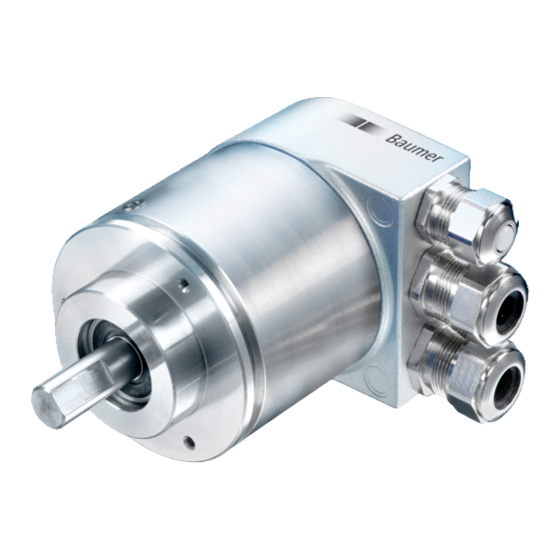
Baumer GXAMW Руководство - Страница 11
Просмотреть онлайн или скачать pdf Руководство для Медиаконвертер Baumer GXAMW. Baumer GXAMW 41 страница. Absolute encoder with powerlink interface
Также для Baumer GXAMW: Руководство (19 страниц), Руководство (26 страниц), Руководство (24 страниц), Руководство (19 страниц)

5. Projecting
All examples in the present manual relate to SIEMENS
®
Step7
, since they are commonly used as PROFIBUS controls. Please proceed in a corresponding way with
other controls.
5.1. Importing the GSD file
To implement the DP-Slave in the projecting software first the attached GSD file must be imported. All
required modifications of basic settings are implemented by parameterization (see "Parameterization"). The
GSD file itself is not modified.
®
software is imported in the hardware window („Extras – install GSD-files"). Prior to the import
Step7
operation the actual hardware project must be closed („Station - close"). Now the encoder appears at right in
the hardware catalogue under „PROFIBUS-DP" – „More field devices" – „Encoder" – (xx corresponding to
the encoder type).
5.2. Encoder bus implementation
Use the mouse to drag text „GxxMW_H IsoM" from the right out of the hardware catalogue to the bus bar. A
window pops up to enter the PROFIBUS node ID that must correspond to the settings of the BCD switch in
the bus cover. All other entries may remain unchanged. Close the entry by OK.
Use the mouse again to drag encoder module „telegram 81" from the right out of the hardware catalogue to
plug-in position 1 of the module window at left below in the hardware window. Do not utilize the universal
module, this is not considered.
5.3. Assigning the user address
If not already done in a previous step or if required at a later date you may alter the PROFIBUS node ID of
the encoder. Upon a double click the window „Properties – DP-Slave" pops up. Click on „PROFIBUS..." and
enter the required node ID here. The node ID must correspond to the settings of the BCD switch in the bus
cover.
5.4. Assigning addresses for input and output data
Later access to encoder input and output data via master software requires assigning E/A addresses to the
input and output data. Click on the encoder icon on the bus bar HW config of Step7 to select the encoder.
Then double-click on module "telegram 81" (plug-in position 1) at left below. The window "Properties - DP-
slave" with tab "Address/ID" pops up (see screenshot).
Enter the respective initial addresses. It is admissible to use Identical or overlapping addresses for output and
input.
Manual_ProfibusDPV2_BIDE_EN.docx
22.11.12
®
controls and the corresponding projecting software
11/41
Baumer IVO GmbH & Co. KG
Villingen-Schwenningen, Germany
