Dover PSG A40 Руководство по эксплуатации - Страница 5
Просмотреть онлайн или скачать pdf Руководство по эксплуатации для Водяной насос Dover PSG A40. Dover PSG A40 19 страниц.

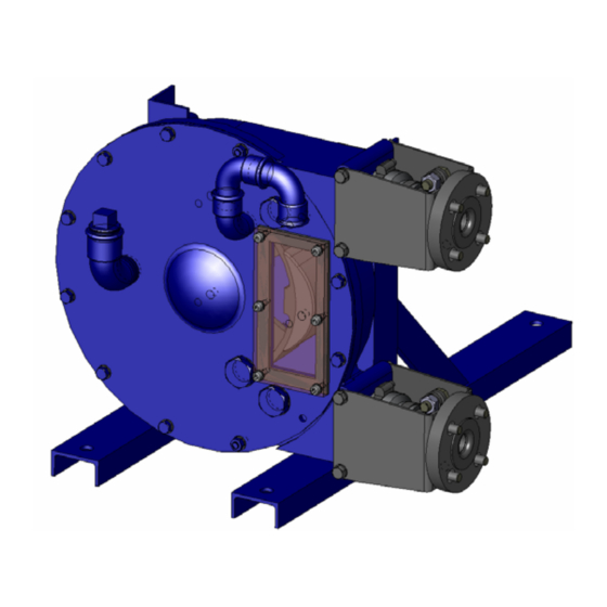
2.1 Operator principle
The pump operates by alternating contraction and
relaxation of a specially designed elastomeric hose.
Two shoes attached 180° apart to a central wheel comp-
ress the hose against the pump body in a fluidtight manner.
Rotation of the wheel causes a flow by displacing the
product into the hose.
The pump body is filled with a special lubricant allowing
shoes to slide easily over the hose, which avoids over-
heating.
2.2 Hose compression
Performance and durability of the hose are guaranteed
by inserting an adequate number of shims under the two
shoes (see § SHIMMING THE SHOES).
2.3 Pumped liquid
Under normal operation, the pumped liquid is only in
contact with the hose and the inserts which must be
compatible with it.
Three different quality elastomeric hoses are available :
• NR (natural rubber) . . . . . . . . . . . White marking
• NBR (perbunan or buna) . . . . . . . Yellow marking
• EPDM . . . . . . . . . . . . . . . . . . . . . Red marking
Inserts are available in AISI 316 stainless steel, in polypro-
pylene (PPH) and in polyfluoride vinylidene (PVDF).
This pumping technology is specially suited to handle
abrasive products.
During the compression stage, abrasive particles may
penetrate the hose wall without damaging it.
Immediately after, these particles are released into the
liquid (the size of particles does not however have to
exceed 15 % of the internal diameter of the hose).
You can contact our Technical Services at any time to ask
for the information you require.
NT 1101-F00 08.10 A40 - AS40 e
2. INSTALLATION
2.4 Pipe diameters
2.5 Piping assembly
Hazardous pressure
personal injury
or property damage.
5/19
The location of the pump in the transfer or recycling circuit
should always be determined so as to reduce the suction
height and length of the piping as much as possible.
The diameter of the pipes must be determined as a func-
tion of their length on the one hand, and the flow and vis-
cosity of the product on the other, so that head loss
remains within design limits. Therefore it is difficult to
give general and precise directions.
However, we recall that it is never prejudicial to plan for
wide piping diameters, particularly regarding the intake.
For the discharge, it is also possible to plan for a diame-
ter equal to that of the pump's orifices, and on the inta-
ke, for a wider diameter if suction is very strong. In the
case of viscous products, the determination of this dia-
meter is very important since the variation of head loss
is proportional to the viscosity and inversely proportional
to the power of 4
th
of the diameter. Therefore a small
reduction of piping diameter can have major consequen-
ces. Our Technical Services are always available to pro-
vide you with precise data if you give them accurate
information or, better still, the installation plans.
WARNING
FAILURE TO RELIEVE THE SYSTEM
PRESSURE PRIOR TO PERFORMING
ANY WORK ON THE PUMP OR THE
INSTALLATION CAN CAUSE PERSONAL
INJURY OR PROPERTY DAMAGE.
can cause
Wherever possible, siphons and reverse slopes in the
suction piping must be avoided and all the gaskets must
be installed with great care to avoid air from entering the
piping.
The elbows must always have a large radius and must
not be assembled too close to the pump flanges, at the
inlet as well as the outlet side.
The stresses exerted by the piping on the pump can
deform the pump parts, increase wear, misalign the bea-
rings and even cause parts to break.
The pipes must be designed to allow thermal expansion
and contraction and be firmly secured (the use of flexi-
ble hoses and expansion loops is recommended).
We recommend placing isolating valves close to the pump
flanges to permit dismantling and replacement without
having to drain the installation. These valves should have
the same diameter as the pipes and, by preference, be a
full bore model.
