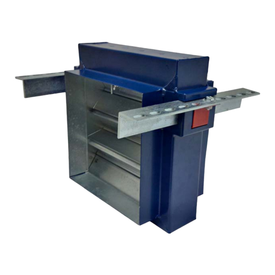
Advanced Air 0160 Series Руководство по установке, эксплуатации и техническому обслуживанию - Страница 12
Просмотреть онлайн или скачать pdf Руководство по установке, эксплуатации и техническому обслуживанию для Противопожарные и дымовые клапаны Advanced Air 0160 Series. Advanced Air 0160 Series 13 страниц. Air control fire damper
Также для Advanced Air 0160 Series: Краткое руководство по эксплуатации (14 страниц)

0160 – OPERATION AND MAINTENANCE
Initial operating check
The 0160 fire damper should only be commissioned once installation has been completed.
The damper should be inspected thoroughly to ensure that it is clean and free of any internal debris before
the damper is tested as per the following instructions;
•
Remove the access door or doors, (on some installations access doors are required on both sides of
the damper to enable the resetting of the damper). If a transportation tie is still fitted to the link, remove it.
•
The 0160 fire damper is fitted with an EML fusible link, this link is provided with a release latch on the
access side of the damper. To test the damper the latch is released allowing the blades to drop and
the link is retained on a pivot opposite to the latch.
•
Before testing the damper, check that the blade pack is sitting level to the drop direction, if they are
sitting uneven before testing this could result in damage to the blades and spring system.
•
Release the latch on the EML, the blades will
drop quickly under the force of the springs
and gravity, ensure that hands and arms are
away from the direction of blade travel.
•
Visually inspect the damper blades to ensure that they are all
interlocked, that the springs are straight and that the bottom damper is
locked into the locking ramp on both sides of the damper. NB;
•
On vertically installed dampers 750 high and above, it is OK for
these not to have springs and locking ramps fitted.
•
To reset the damper, the bottom blade will need to be pushed away from the locking ramp, then
keeping the bottom blade level push the blade pack upwards into the top of the damper. When the top
has been reached the EML fusible link can then be swung into position and secured with the latch. NB;
•
For larger dampers independent supports may be required to hold the blade pack in position
whilst securing the latch.
•
Dampers 149mm and under will have a ring pull fitted to enable the blade to be pulled away from
the locking ramps, on these sizes the release latch is on the opposite side of the locking ramps.
This is the reason access doors are required on both sides of the damper.
•
Refit the access door and complete any relevant reports.
Release latch
Bottom blade
locked into ramp
Maintenance
0160 fire dampers are installed as a life safety product and it is essential that they are always maintained so
they are in a clean working condition. In accordance with BS9999 Annex W.1 maintenance and inspection
should be undertaken annually.
Maintain the dampers as follows;
•
Remove the access door to internally inspect the damper.
•
Visually inspect all damper components for signs of corrosion, obstructions and build-up of dirt/dust.
•
Remove any obstructions, wipe away all dirt and dust from the damper blades, sides and duct surfaces.
•
Examine the EML fusible link to ensure that no corrosion has occurred.
•
If the EML fusible link is required to be replaced, then should be done as follows:
•
Use independent supports or hold the damper blade pack in position.
•
Release the EML latch, the link will now drop and pivot on the opposite side.
•
To release the link from the retaining bracket, hold the link and lift it upwards in its retaining slot
then pull it away from the bracket.
•
To fit a new link push it into the slot of the bracket on the non-access side of the damper.
•
Rotate it upwards and secure with the release latch
•
Test and check the damper by the method detailed in the 'Initial Operating Check'.
•
Refit the access door and complete maintenance reports as appropriate.
12
