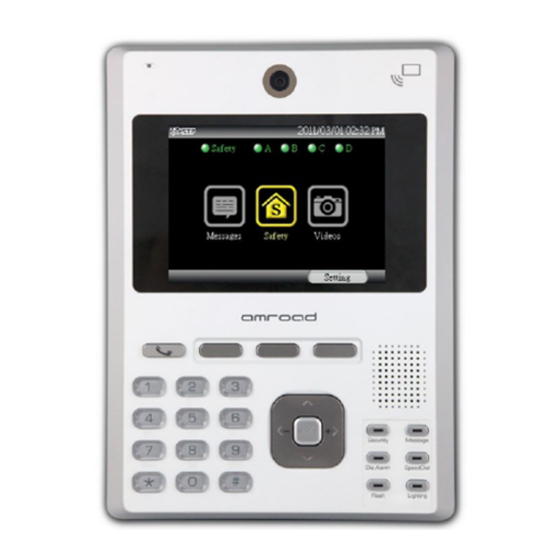
Amroad ID5101 Руководство по быстрой установке
Просмотреть онлайн или скачать pdf Руководство по быстрой установке для Система безопасности Amroad ID5101. Amroad ID5101 4 страницы. Home station
Также для Amroad ID5101: Руководство по установке (20 страниц)

Package Contents
These items are included in your Video Indoor Station package. Check this list before
installation to ensure that you have received all items.
1. Video Indoor Station
2. Back Plate
3. Wall mounted screw pack
4. Screw Pack (2 pieces)
5. Screw for Earth Wire
6. H-type Terminal Connector for
Power Wire (1 pieces)
7. Main RFID Card
8. CD-ROM (containing Manual,
QIG, QOG, and Search Tool)
9. I/O Cable (3 pieces)
10. Relay Board (2 pieces)
11. Quick Installation Guide &
Quick Operation Guide
Please contact your dealer immediately if any item(s) is missing.
Rear Panel & GPIO Connectors
NOTE: To avoid electrical shock, we strongly suggest that connecting DC power to
ID5101 after ID5101 has installed on the wall.
Installing Video Indoor Station
Due to the view angle of the camera is limited, therefore the installation position for
Video Indoor Station is crucial. In order to get a better view, the view angle of this door
phone should be around 105. Also the height of the lens position is suggested at the
height of 155 cm according to building conditions.
Please reserve the space for junction wiring in the wall, you may refer to the embedded box
dimension as diagram below.
800-0000007-00-00
Installing Procedures
1. Screw the Back Plate on the wall.
Please pull out the DC wires and Ethernet cable pass through the back plate. Then,
connect them with the Video Indoor Station after securing the Back Plate on the wall.
If necessary, please connect the Earth wire to the screw as diagram below.
For more GPIO application, please refer to Safety/Security Application in next page
2. Connect the DC +12V wires and Ethernet cable.
Plug the DC wire connector of ID5101 to Power-Connecting connector, and connect
Ethernet cable to ID5101 as diagram below.
Be careful when you are connecting the DC wires, please check the power condition and
turn off the general power switch before you start to connect the wires.
3. Screw the Video Indoor Station with Back Plate.
Before connecting to Safety and Security Devices
GPIO connectors and I/O Pin Assignment and Wire Color
There are three GPIO connectors on the rear panel of your Video Indoor Station.
These GPIO connectors are used to connect with Safety and Security devices.
Before you begin to connect other devices to the ID5101, the I/O wires and their
colors for GPIO connectors are illustrated as pictures below.
GPIO connectors and I/O Pin Assignment and Wire Color
1
After connecting the wires and cables properly,
then screw the 2 screws that come with the
package into the front panel. Please double check
all the installation procedures again, then you may
power on the general power switch to start the
configuration procedures.
