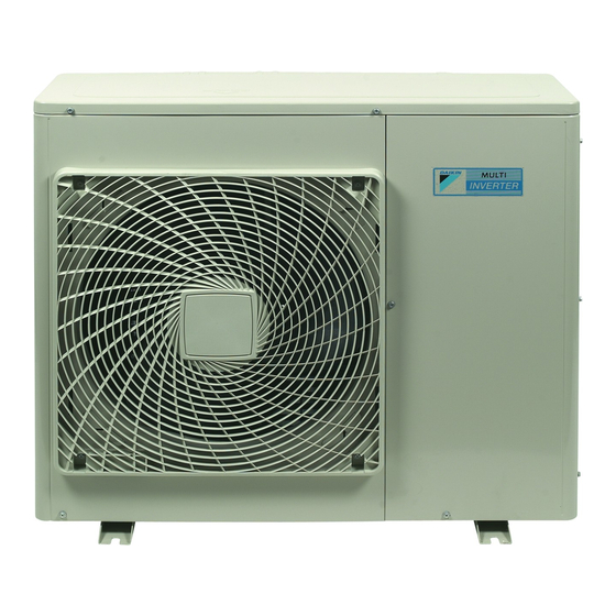
Daikin 4MXS80E3V3B2 Руководство по установке - Страница 13
Просмотреть онлайн или скачать pdf Руководство по установке для Кондиционер Daikin 4MXS80E3V3B2. Daikin 4MXS80E3V3B2 16 страниц.

Night quiet mode setting
The night quiet mode setting requires initial programming during
installation. Explain night quiet mode, as described below, to the
customer, and confirm whether or not the customer wants to use
night quiet mode.
Night quiet mode function
The night quiet mode function reduces operating noise of the outdoor
unit at nighttime. This function is useful if the customer is worried
about the effects of the operating noise on the neighbours.
Running units in night quiet mode however, reduces the cooling/
heating capacity.
Setting procedure
Remove the SW5 jumper switch.
S102
S2
A
1
2
3
4
1
5
1
Once the settings are complete, reset the power.
Install the removed jumper switch as described below.
NOTE
This switch will be needed to later disable this setting.
1
Jumper switch
2
After removing
COOL/HEAT mode lock <S15>
arrow view A in this paragraph)
Use the S15 connector to set the unit to only cool or only heat.
1
Setting to only heat (H): short-circuit pins 1 and 3 of the
connector S15.
2
Setting to only cool (C): short-circuit pins 3 and 5 of the
connector S15.
A
The following specifications apply to the connector housing and pins
(JST products):
Housing
VHR-5N
Pin
SVH-21T-1,1
Remark that bridging connections are available as spare parts.
Check the dedicated spare parts list.
NOTE
Forced operation remains available, whatever the
mode setting that has been locked.
Night Quiet Mode setting switch SW5
1
(See
figure 7
1
2
S15
1
3
5
Test run and final check
Before starting the test run, measure the voltage at the primary
side of the safety breaker. Check that it is 230 V.
Check that all liquid and gas stop valves are fully open.
Check that piping and wiring all match. The wiring error check
can be conveniently used for underground wiring and other
wiring that cannot be directly checked.
NOTE
Remark that during the first running period of the unit,
required power input may be higher than stated on the
nameplate of the unit. This phenomenon originates
from the compressor that needs elapse of a 50 hours
run in period before reaching smooth operation and
stable power consumption.
Wiring error check
This product is capable of automatic correction of wiring errors.
Press the wiring error check switch SW3 on the outdoor unit
service PCB. Approximately 15–20 minutes after the switch is
pressed, the errors in the connection wiring will be corrected.
However, the wiring error check switch will not function the first
3 minutes after the safety breaker was turned on, or depending
on the outside air condition (See Note
S102
S2
A
1
2
1
3
4
5
The service monitor LEDs indicate whether or not correction is
possible, as shown in the table below. For details about how to read
2
the LED display, refer to the service manual.
If self-correction is not possible, check the indoor unit wiring and
piping in the usual manner.
and
LED
1
Flashing one after another
Status
One or more of LEDs
2 on page
1
Wiring error check switch SW3
2
3
4
5
All flashing
Automatic correction is impossible
Automatic correction is completed
Abnormal stop (See Note
1 to 5 are ON
11).
Message
4 on
page
11)
Installation manual
10
