AMS AS5147P Руководство по эксплуатации - Страница 4
Просмотреть онлайн или скачать pdf Руководство по эксплуатации для Адаптер AMS AS5147P. AMS AS5147P 13 страниц. Usb interface & programming box
Также для AMS AS5147P: Руководство пользователя (13 страниц)

AS5147P Adapter Board
2
Board description
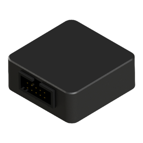
The PCB can either be connected to an external microcontroller or to the USB I&P Box which is
available on our webpage.
P1 has to be populated with a 2x8 pin header and is required for power supply as well as SPI,
ABI, UVW/PWM interfaces.
The connector JP1 allows to select between 5V or 3.3V operation.
R1 and R2 are 0 ohm resistors in 0603 package. Depending on the supply voltage either R1 or
R2 has to be populated. For 5V operation R1 has to be populated and R2 has to be removed
(default case). Vice versa for 3.3V operation.
Figure 2: AS5147P adapter board
P1 connector
(Not populated)
4x2.6mm
Mounting holes
ams Eval Kit Manual, Confidential
[v1-0] 2015-Jan-14
(USB I&P
Box)
JP1 connector
(Selecting supply
voltage)
AS5147P
Page 4
Document Feedback
