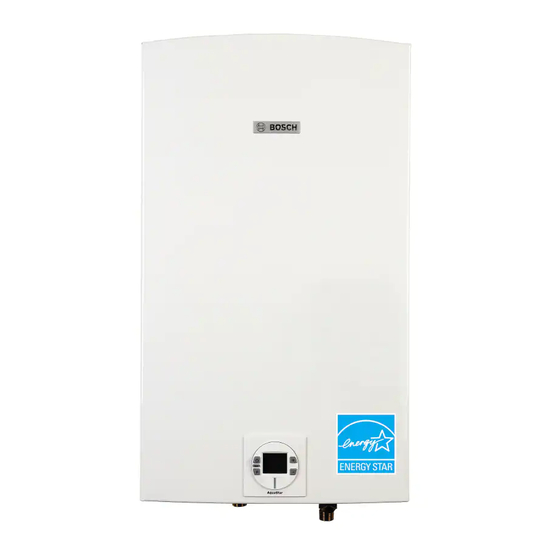
Bosch Evolution 500 Бюллетень технического обслуживания
Просмотреть онлайн или скачать pdf Бюллетень технического обслуживания для Посудомоечная машина Bosch Evolution 500. Bosch Evolution 500 2 страницы. Removing and replacing water valve
Также для Bosch Evolution 500: Руководство по эксплуатации (40 страниц), Руководство по установке (6 страниц), Сервисный бюллетень (2 страниц), Бюллетень технического обслуживания (2 страниц), Сервисный бюллетень (2 страниц)

Technical Service Bulletin:
C6 & C7 Error Code Troubleshooting
Models: C1210ESC, C1210ES, C1050ES, C950ES, 940ES, 940ESO, 830ES, 2400ES,
2700ES, 715ES, C800ES, C920ES/ESC, Integra 500, Evolution 500
Introduction
This procedure must be performed by a qualifi ed technician.
DANGER!
120 VAC present in wire connections. Use caution
when testing.
Follow the procedures below and report results to Bosch Technical
Support. This will assist in determining the cause and solution to the
problem.
C6 and C7 error codes
These errors are fan-related error codes with the following
explanations:
C6 error indicates the primary fan rotation is too low during
operation.
C7 error indicates there is no primary fan rotation sensed
during an attempted start-up.
Primary Fan Assembly
The primary fan is a 120 volt AC fan that receives power from
the main control board.
The primary fan has its own built-in circuit board which relays
information and signals back to the control board.
Tools needed:
Phillips head screwdriver
Digital Multi-meter
Procedure
1.
Press the reset button on the control panel of the heater to
attempt to clear the error code. If the error code does not reset
or continues to reoccur, proceed with the following trouble-
shooting steps.
2.
Confi rm that the exhaust vent is not blocked and does
not exceed the specifi ed maximum length as shown in the
installation manual.
3.
Ensure that the 3 foot minimum separation between air intake
and exhaust vents is met (applies to a twin pipe vent system).
4.
Verify the heater is plugged into a properly grounded 120V AC
power supply.
5.
Supply the heater with a steady supply voltage. It is
recommended to supply electricity from a dedicated electrical
circuit with no other major appliances on the same circuit.
6.
Shut off power to the heater and unplug from electrical outlet.
Remove cover per installation manual.
7.
Remove the black plastic intake (Fig.1, pos.1) that is secured
with three Phillips head screws to the fan (Fig.1, pos.2).
8.
Check the wire connection to the fan. The wire connection is
located on the back, left hand side of the fan housing. (Fig. 2).
Figure 1
