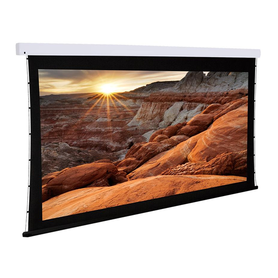
Dragonfly DFM-TAB-120 Руководство по установке - Страница 9
Просмотреть онлайн или скачать pdf Руководство по установке для Проекционный экран Dragonfly DFM-TAB-120. Dragonfly DFM-TAB-120 17 страниц. Dfm-tab screens
Также для Dragonfly DFM-TAB-120: Руководство пользователя (8 страниц)

6. Control Setup
6.1. Control Wiring Diagram
6.2. IR Control (With Optional IR Receiver Extension)
The IR receiver built into the front of the screen works with remotes up to 26ft away at a maximum angle of 30°.
The included external IR receiver can be connected to the EXT IR port if additional range is needed.
To use the external receiver, plug it into the screen and have an assistant hold the receiver in different mounting
locations until the remote works reliably from where it will be used most. Mount the IR receiver using the adhesive
foam tape on the back.
Note: The included external IR receiver is proprietary to Dragonfly projection screens. Other IR receivers will not
work correctly.
6.3. 12 Volt DC Trigger Cable
Screens may be lowered and raised by a 12 volt trigger signal sent from other equipment like a projector. A propri-
etary, 33ft cable is included for connecting a standard 1/8" (3.5mm) mono mini 12 volt trigger port to the TRIG port
of the projection screen.
12 volt trigger operates by sending a 3-12V DC signal to the screen when the projector turns on. The screen will
lower and remain lowered until the projector is turned off and the voltage drops to 0v (zero).
Other control methods may be used with 12V trigger. However, the screen will remain lowered for use if voltage is
present on the trigger while an attempt is made to close the screen.
Important! The projection screen still requires external AC power for operation. The 12 volt trigger connection will
NOT power the screen. Plug the AC power cord into a suitable outlet supplying 120V AC.
6.4. Manual Wall Switch
The included wall switch may be surface mounted near the projection screen for manual control. A 10ft RJ12 cable
is included to connect the switch to the screen. This cable may be replaced with a custom Cat5e/6 cable if longer
runs are required due to the location of the switch. See the next page for complete instructions.
6.5. RS232 Serial Control
Pins 1 and 2 on the EXT CTRL port may be connected to a control system serial output for one-way control.
Please see the DFM Motorized Screen Control Protocol for driver and command information, available on the Sup-
port tab at the DFM-NTT product page at www.SnapAV.com. The diagram illustrating the correct pins to use for
RS232 and instructions to extend the wiring from the screen to the control system are on the following page.
6.6. Contact Closure/Relay Control
The Dragonfly motorized screen may also be controlled via contact closure or relay control. Using the same
conductors that are used for the wall switch, momentarily short the Common wire to the Up, Down, or Stop
wire for the desired operation. The diagram illustrating the correct pins to use and instructions to extend the wiring
from the screen to the control system are on the following page.
www.snapav.com Support: 866.838.5052
External IR Receiver
or
Mono Cable
for Remote Trigger
Wall Switch
From Control System
DFM-TAB Installation Manual
(RS232 or Contact
Closure)
Pg. 9
