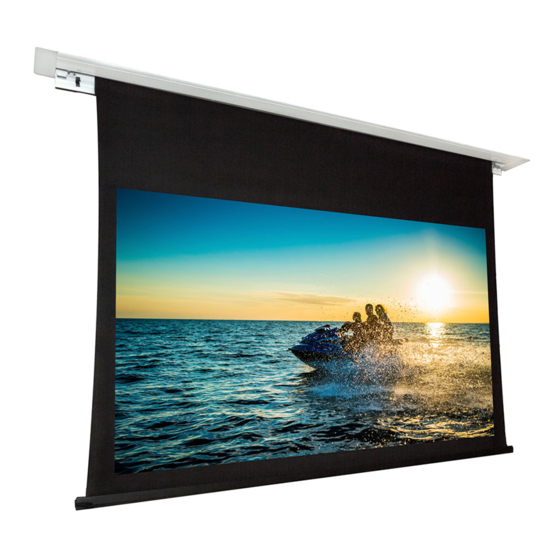
Dragonfly DFRM-NTT-130-MW Руководство по установке - Страница 9
Просмотреть онлайн или скачать pdf Руководство по установке для Проекционный экран Dragonfly DFRM-NTT-130-MW. Dragonfly DFRM-NTT-130-MW 17 страниц. Recessed in-ceiling motorized projection screen

Step 7. Connect Control Wiring
(Gold pins facing up)
RF Remote
Use the included remote for control of the screen from any direction. Remote uses AAA batteries,
included. If your remote will not operate the screen after installation, it may need to be paired:
1.
Find the RF PAIRING button inside the casing (far left side) and hold it down for 5 seconds, until the screen will
drops approximately 1". Release the button.
2.
Press and hold the RF PAIRING button for another 5 seconds.
3.
After 5 seconds, also begin pressing the "UP" arrow on the remote. After an additional 5 seconds, the remote
should be paired and the screen will move.
IR Receiver
Connect the included IR receiver to the EXT IR port for IR control up to 26ft away and at a maximum
angle of 30°. Mount the receiver using the adhesive foam tape on the back. (Note: The included IR
receiver is proprietary to Dragonfly projection screens. Other IR receivers will not work.)
3-12V DC Trigger
Connect the included 33 foot trigger wire from the TRIG port on the screen to the control out port
on a compatible projector for automatic control based on the projector.
RS232 Serial Control
Use pins 1 and 2 on the EXT CTRL port for one-way control. See the DFM Motorized Screen Control
Protocol for driver and command information, available on the product page support tab.
To connect wiring, either cut the included 10 foot RJ12 control cable and splice to the correct wires
or terminate a cable using a 6P6C RJ11/12 connector.
Contact Closure/Relay Control
The Dragonfly motorized screen may also be controlled via contact closure or relay control.
Momentarily short the COMMON wire to the UP, DOWN, or STOP wire for the desired operation.
The screen will stop automatically once a limit is reached, or the STOP function may be used to
stop at any desired position.
To connect wiring, either cut the included 10 foot RJ12 control cable and splice to the correct wires
or terminate a cable using a 6P6C RJ11/12 connector.
EXT Control Connection
1 2 3 4 5 6
1 2 3 4 5 6
Pin 6 - Up
Pin 5 - Down
Pin 4 - Stop
Pin 3 - Common
Pin 2 - RS232 Data Receive (RXD)
Pin 1 - RS232 Data Transmit (TXD)
DFRM Installation Manual
External IR Receiver
3.5mm Mono for
remote 3-12V DC
trigger
Pg. 9
