Advanced Electronics MXPro4 Mxp-007F Руководство - Страница 5
Просмотреть онлайн или скачать pdf Руководство для Реле Advanced Electronics MXPro4 Mxp-007F. Advanced Electronics MXPro4 Mxp-007F 10 страниц. Relay output cards

1.3 Installing the Mxp-008 in the Mx-4200/Mx-4400/Mx-4800
1.3.1 Mounting the Card
The card mounts on 4 pillars in the top left hand corner of the
control panel chassis adjacent to the Mx4200/Mx 4400 base card.
See diagram opposite.
Use the four M3 screws supplied to securely affix the card to the
chassis.
It is not possible to install the Mxp-008 in this position if either the
Mxp-021 Sounder Splitter or the Mxp-028 Modem is already
installed.
1.3.2 Internal Wiring
Use the supplied 10-way single in line ribbon cable to connect the
relay card, via the latched header – PL1, to the adjacent 10-way
latched header on the base card.
1.4 External Wiring
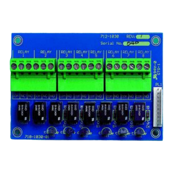
The picture below shows the terminal block
positions for each relay output.
Relay positions 1 and 2 provide NO / NC
changeover contacts. Relay positions 3 – 8
provide NO contacts only (Mxp-008 Only).
Install cables suitable for the application and
degree of fire protection required. These circuits
are SELV type.
If additional knockouts are required on the Mx-
4200 or Mx-4400 then use the deeper back box
(Mxm-020) or use the Termination Enclosures
(Mxm-028 or Mxm-029) as appropriate.
RELAY
RELAY
RELAY
RELAY
1
2
3
4
COM NC
NO COM NC
NO
COM NO COM NO COM NO
www.acornfiresecurity.com
RELAY
RELAY
RELAY
RELAY
5
6
7
8
COM NO COM NO COM NO
www.acornfiresecurity.com
All electrical wiring installation work should be carried out in
accordance with the code of practice applicable in the
country of installation.
To maintain electrical integrity of the SELV wiring on the
output lines all SELV wiring should be segregated from the
LV mains wiring and be wired using cable with insulation
suitable for the application.
To minimise the effects of EMC interference all data wiring
circuits should be wired with a twisted pair of conductors with
a cross sectional area suitable for the loading conditions.
In areas where cabling may come into contact with high
frequency interference, such as portable radio transceivers
etc. the output wiring cable should be of a twisted pair
construction within an overall screen. The screen should be
terminated to one of the dedicated earth studs available in
the panel (refer to panel manual for positions).
NB: Minimum / Maximum cable size for all connections is
limited to 0.35mm² / 2.5mm² (22-14AWG).
Mxp-008
Base Card
M3 Fixing
Screws
5
