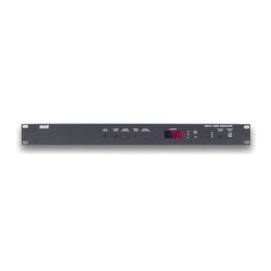
DRAKE VM2551 Руководство по эксплуатации - Страница 4
Просмотреть онлайн или скачать pdf Руководство по эксплуатации для Модулятор DRAKE VM2551. DRAKE VM2551 12 страниц. Commercial video modulator
Также для DRAKE VM2551: Руководство по эксплуатации (10 страниц)

4
Table of Contents / Description / Specifications
TABLE OF CONTENTS
2
Caution Statements
2
Important Safety Instructions
4
Table of Contents / Description / Specifications
5
Front/Rear Panel Controls and Indicators
DESCRIPTION
The R.L Drake VM2050 and VM2550 Video Modulators are high quality, vestigial
sideband units with synthesized visual and aural carriers. They are designed to accept
NTSC video and audio baseband signals from a satellite receiver or similar equipment.
Front panel video and audio level controls with accompanying modulation
indicators permit easy setup of the proper modulation levels. The A/V ratio and
RF output level controls are also provided on the front panel. A rear panel EAS
alternate IF input is also provided.
Synthesized operation provides complete frequency agility, allowing front panel
selection of any standard CATV channel from 2 to 78 (VM2551) and T7 to 78
(VM2050) . FCC required offsets for aeronautical channels are automatically
provided for each channel that requires an offset. For special applications, IRC or
HRC CATV frequencies or off-air broadcast frequencies can be selected from the
front panel.
SPECIFICATIONS - VM2050 / VM2551
Connector:
Impedance:
Return Loss:
Video Input Level:
Signal-to-Noise Ratio:
Differential Gain:
Differental Phase:
Over-modulation Indicator:
L/C Delay:
Connector:
Impedance:
Return Loss:
Channel Modes:
Power Level Range:
Video Flatness:
Carrier-to-Noise:
Broadband Noise:
Spurious Outputs:
Aural/Visual Carrier Ratio:
AC Power:
Fuse:
Temperature Range:
Dimensions (WxDxH):
Weight:
VIDEO INPUT
"F" Female
75 Ω
18 dB
0.7 volt Peak-to-Peak
58 dB
2.0%
1.0 degree
87 to 92%
Per FCC Requirements
RF OUTPUT
"F" Female
75 Ω
12 dB
CATV (STD,IRC,HRC) UHF, VHF
(SUB VM2050 only)
+50 to +60 dBmV (in 0.2 dB increments)
fv-0.5 to fv+4.2 MHz : 1.5 dB p/v
-63 dB
-77 dBc
-63 dBc
-15 ± 5 dB
GENERAL
117 VAC ± 10%, 60 Hz, 23W max
0.4A Type T 250 V
32 to 122 °F (0 to 50 °C)
19.0 x 14.25 x 1.75 in
(482.6 x 361.95 x 44.45 mm)
7 lbs. (3.18 kg)
6
Operation
7
Adjustments
8
Channel Assignments
A high quality IF SAW filter with FCC predistortion eliminates adjacent channel
interference and provides optimum delay characteristics.
A manual or auto-switching alternate IF input, labeled EAS input, is provided for
connection of an Emergency Alert System 44 MHz IF signal. When the EAS IF signal
appears at the EAS input, the main video and audio modulated IF is replaced by
the EAS input signal.
The EAS/Alternate IF feature allows a choice between manual and automatic
selection of the EAS/ALT IF input signal. This is done through a 3 position terminal
strip on the rear of the unit. In the manual mode the EAS/ALT IF feature is
activated by a contact closure switch, which completes a ground connection. In
the automatic mode, two positions on the terminal strip are jumpered together
enabling an automatic detection circuit in the unit. When an EAS/ALT IF signal is
routed to the EAS/ALT port the unit automatically switches to that alternate signal.
Connector:
Input Impedance:
Input Level:
Frequency Range:
Frequency Response:
Total Harmonic Distortion:
Signal-to-Noise Ratio:
Over-modulation Threshold:
Input/Output Connector:
Aural Frequency:
Visual Frequency:
Composite IF Output
Aural:
Visual:
Input/Output Impedance:
Input/Output Return Loss:
EAS/Alternative IF
Connector:
Input Level:
Switch Isolation: Greater than 60dB
VM SERIES VIDEO MODULATOR
MONO AUDIO
RCA
Greater than 10k Ω, unbalanced
0.5 to 4.0 volt Peak-to-Peak
50 Hz to 15 kHz
± 0.5 dB
1% @ 25 kHz deviation
59 dB
25 ± 2 kHz peak deviation
IF
"F" Female
41.25 MHz
45.75 MHz
+20 dBmV
+35 dBmV
75 Ω
16/15 dB
"F" Female
+30 dBmV @ 45.75 MHz
