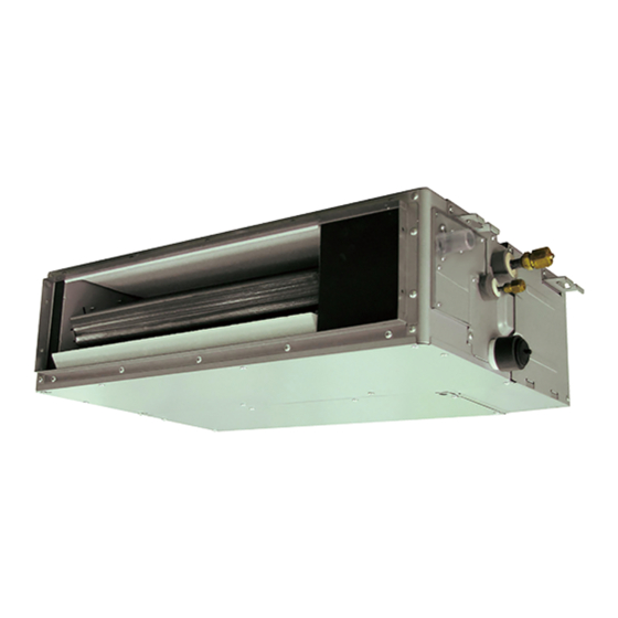
AirStage ARXK14GALH Руководство по установке - Страница 4
Просмотреть онлайн или скачать pdf Руководство по установке для Кондиционер AirStage ARXK14GALH. AirStage ARXK14GALH 19 страниц. Indoor unit (duct type)

• Decide the mounting position with the customer as follows:
(1) Install the indoor unit on a place having a suffi cient strength so that it withstands
against the weight of the indoor unit.
(2) The inlet and outlet ports should not be obstructed; the air should be able to blow all
over the room.
(3) Leave the space required to service the air conditioner.
(4) A place from where the air can be distributed evenly throughout the room by the unit.
(5) Install the unit where connection to the outdoor unit is easy.
(6) Install the unit where the connection pipe can be easily installed.
(7) Install the unit where the drain pipe can be easily installed.
(8) Install the unit where noise and vibrations are not amplifi ed.
(9) Take servicing, etc., into consideration and leave the spaces. Also install the unit
where the fi lter can be removed.
3.2. Installation dimensions
Provide a service access for inspection purposes.
Do not place any wiring or illumination in the service space, as they will impede service.
Installation Dimensions
Strong and durable ceiling
Left
side
150 mm or
more 1
1 400mm or more when drain from drain pipe
• When intaking air from back
5 mm or more
20 mm or more
Service access
• When intaking air from bottom
5 mm or more
20 mm or more
Service access
Adjust the wind direction in the room depending on the shape of blow out opening.
[ Top view ]
Service space
*: Above 100mm When intaking air from bottom
En-3
Indoor unit
400 mm
or more
300 mm or more
Air
Ceiling
Floor
100 mm or more
Air
Ceiling
400 mm or more
Air
Service access
Air
3.3. Installation the unit
Install the air conditioner in a location which can withstand a load of at least 5 times the
weight of the main unit and which will not amplify sound or vibration. If the installation
location is not strong enough, the indoor unit may fall and cause injuries.
If the job is done with the panel frame only, there is a risk that the unit will come loose.
Please take care.
3.3.1. Unit installation example
Connect the locally purchased duct.
(1) Inlet side
• Connect the duct to the locally purchased inlet fl ange.
• Connect the fl ange to the body with the locally purchased tapping screws.
• Wind the inlet fl ange connecting to the duct with the aluminum tape etc. to avoid the
air leakage.
When the duct is connected to inlet side, remove contained fi lter and surely attach
locally purchased fi lter at inlet opening.
(2) Outlet side
• Connect the duct with adjusting inside of outlet fl ange.
• Wind the outlet fl ange connecting to the duct with the aluminum tape etc. to avoid the
air leakage.
• Insulate the duct to avoid the dew condensation.
Right
side
To prevent people from touching the parts inside the unit, be sure to install grilles on
the inlet and outlet ports. The grilles must be designed in such a way that cannot be
removed without tools.
Check that duct work does not exceed the range of external static pressure of
equipment.
Make sure to insulate ducts to avoid the dew condensation.
Make sure to insulate between ducts and walls if metal ducts are used.
Please explain handling and washing methods of locally purchased materials to the
customer.
To prevent people from touching the parts inside the unit, be sure to install grilles on
the inlet and outlet ports. The grilles must be designed in such a way that cannot be
removed without tools.
When connecting the duct to the outlet port of the indoor unit, be sure to insulate the
outlet port and the installation screws to prevent water from leaking around the port.
Set the static pressure of AR07/09/12 model to 0 to 30 Pa.
Set the static pressure of AR14/18/24 model to 0 to 50 Pa.
Replace the cover as follows.
• Remove the screws, and then remove cover.
• Install the cover with the screws as shown in the illustration below.
AR07/09/12/14
AR18
AR24
Control
box
WARNING
CAUTION
CAUTION
Model
screw
Screw
6
7
8
Cover
