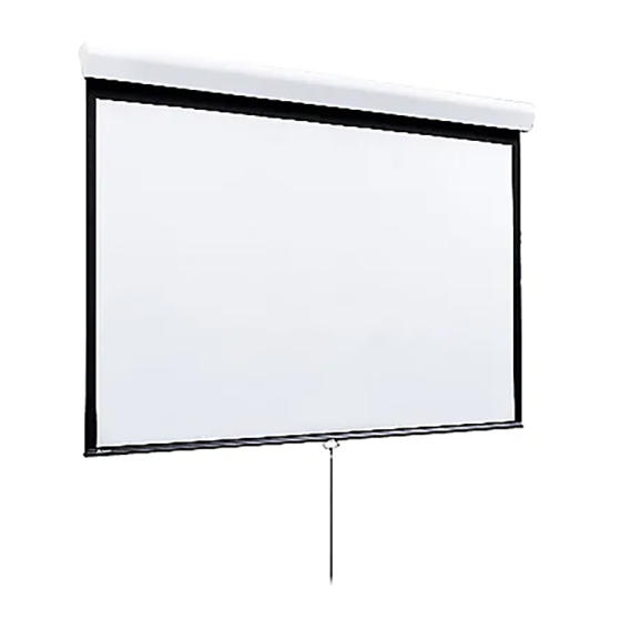
Draper Silhouette Series M Инструкции по установке и эксплуатации - Страница 2
Просмотреть онлайн или скачать pdf Инструкции по установке и эксплуатации для Проекционный экран Draper Silhouette Series M. Draper Silhouette Series M 2 страницы. Manually operated projection screens

Silhouette/Series M and Series C by Draper
(1) pan head screw and (1) locking nut. (Make sure "Z" Clip is ori ent ed 90°
to angle adapt er.)
Locking screw
"Z" Clip*
Angle adapter*
Pan head screw
Hex nut
Extension bracket
* Provided with screen
Side view of assembled extension bracket
Wall mount the ex ten sion brack ets to wall, making sure they are level and
ver ti cal ly plumb. In stall er must in sure fas ten ers are of ad e quate strength
and suit able for cho sen mount ing sur face. Back out the top stop screw until
it is fl ush with front side of an gle adapt er.
En gage the lip on back of screen case with lip of "Z" Clip and gen tly pull
down to fully en gage case to brackets. Screw in stop screw on each bracket
to lock screen case in place.
Locking screw
Wall bracket*
Angle adapter*
Extension
bracket
*Supplied with screen
Operating Instructions
Series M Spring Operated Screen: To lower picture sur face, pull screen
down to de sired position. Hes i tate—then allow screen to slightly retract very
slowly until it locks in place.
To raise picture surface, pull down on the pull bail, then raise quickly, as
a window shade. Keep control of the picture sur face. Do not allow it to roll
un con trolled into the case, or dam age is sure to result.
Series C Crank Operated Screen: To lower screen sur face, attach the
crank handle to the "U" joint stud located on the left hand side of the screen.
With the crank handle in its operating position, rotate coun ter clock wise. An
internal pin within the gear box will stop the screen when fully extended.
The crank handle can be removed if desired. The shipping support brackets
must be removed from each end of dowel during initial operation.
To raise screen surface, attach the crank handle to the "U" joint stud located
on the left hand side of the screen. With the crank handle in its operating
position, rotate in a clockwise direction. An internal pin within the roller will
stop the screen when fully retracted. The crank handle can be removed if
desired.
Angle adapter
90˚
Wall bracket
Pan
head
screw
Extension Arm
Front view of assembled
extension bracket
www.draperinc.com
Removing Case Fascia
Case fascia is removable to access roller assembly. To remove fascia, depress
outward the spring lip located inside lower front corner of screen case and
pull lower corner of fascia outward. Repeat this at right end of case. Support
fascia from center and rotate lower front edge upward ap prox i mate ly 40° to
disengage the Roll-Lok hinge at the top front of screen case. Fascia can
now be completely removed from case.
To install fascia, generally reverse instructions above making sure the Roll-
Lok hinge is completely engaged before rotating fascia down towards the
closed position. Depress spring clips outward, push lower corners of fascia
inward until lips of spring clips hook behind fascia.
Case Dimensions
Silhouette/Series M
1½"
Viewing Surface
Silhouette/Series C
3
2
/
"
8
1
2
/
"
8
Tab-Tension Adjustment Procedure for Silhouette/Series C
➀ Determine which side requires adjustment.
➁ Secure dowel with one hand.
Caution: Do not touch or bend surface.
➂ Using Philips-head screwdriver,
depress spring-loaded adjustment
screw (see drawing) and slowly turn
clockwise to tighten tension, or
counterclockwise to loosen tension.
The screw adjusts in ¼ turn
increments. Adjust only
one increment (¼ turn).
➃ If problem is not corrected, leave
screen in position for 24 hours to allow
surface material to stretch into position.
➄ If problem still is not corrected, repeat steps ➁ and ➂.
(765) 987-7999
Page 2 of 2
4¾"
6"
Tensioning
Cable
Dowel
Adjustment
Screw
