CARLO GAVAZZI EM 26 Руководство
Просмотреть онлайн или скачать pdf Руководство для Измерительные приборы CARLO GAVAZZI EM 26. CARLO GAVAZZI EM 26 4 страницы. Compact 3-phase energy analyzer
CARLO GAVAZZI
Carlo Gavazzi Controls SpA,
Via Safforze, 8 - 32100
Belluno (Italy)
A u t o m a t i o n
C o m p o n e n t s
Tel. +39 0437 931000,
Fax +39 0437 931021
EM2696 IM ENG ITA ESP 8020796 080808
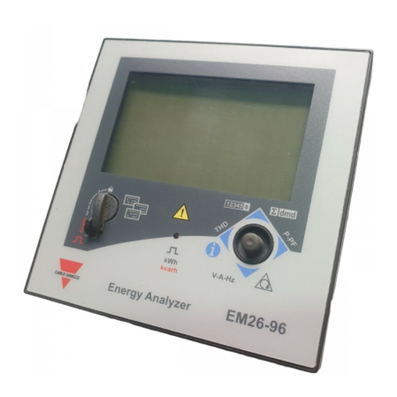
EM26 96
"Compact 3-phase Energy Analyzer"
Fig. 1
Fig. 2
LED
TAB 1
1
2
3
ENG- Displaying of water cubic meters
ITA- Visualizzazione contatore metri cubi acqua
ESP- Visualización metros cúbicos de agua
ENG- Displaying of gas cubic meters
ITA- Visualizzazione contatore metri cubi gas
ESP- Visualización metros cúbicos de gas
ENG- Displaying of phase-to-neutral system voltage
ITA- Visualizzazione tensione fase-neutro di sistema
ESP- Visualización tensión sistema fase a neutro
ENG- Displaying of phase-to-phase system voltage
ITA- Visualizzazione tensione fase-fase di sistema
ESP- Visualización tensión sistema fase a fase
ENG- Displaying of max values
ITA- Visualizzazione valori massimi
ESP- Visualización valores máx.
ENG- User ID
ITA- Identificatore Utente
ESP- ID, identificación de usuario
ENGLISH
I I JOYSTICK AND KNOB FUNCTIONS
Refer to fig.1. In the measurement mode: 1) push for at least 3 seconds to enter pro-
gramming; 2-3-4-5) scroll the measurement and info pages (see tab. 5) according to
table 3; In the "CoLour" mode set to CoL or CoL 3, any pressure of the joystick enables
the back-light for at least 60 seconds. In the programming mode: 1) enter the modified
value and access to the menus; 2-3) increases/decreases the values to be modified 4-5)
scroll the menus. The knob (see fig. 2), prevents from accessing the programming mode
when in
position. It allows the direct access to the predefined measuring pages (see
table 3) when in "1", "2" and 3 positions. The measuring pages change according to the
selected "APPLiCAt" parameter. The frontal red LED (fig.1) flashes proportionally to the
active imported energy consumption if the selector is in "
- 1 - 2" position, and to the
reactive inductive energy consumption when in position "3" (kvarh). Any kind of nega-
tive (exported) energy and power will not be managed by the front LED.
I I DISPLAY LAYOUT
The display is divided into 3 lines (as illustrated by the dotted lines in the TAB 1 table). The
engineering units are referred to the variables shown in the relevant lines, while the "nega-
tive" symbols (∑, dmd) refer to all the variables displayed in the second and third line of the
display. To improve the display legibility, EM26 uses some symbols (see TAB 1). In case of
"OVERFLOW", the instrument displays "EEEE": at the same time the DMD calculation, the
hour-counter and the energy meters functions are inhibited and the alarm outputs are acti-
vated. The indication "EEEE" in a single phase variable automatically implies the overflow
condition of the relevant system variable, and the PF indication is forced to "0.000".
I I MEASUREMENT PAGES AND INFORMATION PAGES
To display and scroll the measurement pages, the joystick is to be moved to directions
2-3-4-5 (see fig.1) according to table 3; To display and scroll the measurement pages
relevant to the meters, the "dmd" and system values, the joystick is to be moved to
direction 2. To display and scroll the current, voltage, single phase, frequency and phase
sequence measurement pages, the joystick is to be moved to direction 3. To display and
scroll the power and phase displacement measurement pages, the joystick is to be
moved to direction 4. To display and scroll the THD current and voltage indications and
all the "info" pages (see tab. 5), the joystick is to be moved to direction 5. According to
the selected "APPLiCAt" parameter, different measurement pages are available (see
tab.3).
I I BASIC PROGRAMMING AND RESET
To enter the complete programming mode the joystick is to be pressed in direction 1
for at least 3 sec. (see fig.1): the knob (see fig.2) is NOT to be in
(with the knob in
this position, the access to programming is allowed only for some of the menus, see
tab. 7), otherwise the programming mode is not allowed. Entering the programming
mode, all the measurements and control functions are inhibited.
00
: only for A, B, C and E applications and only with the knob in position
and
moving the joystick towards direction 1 (see fig. 1), it will be possible to reset the
"Wdmd max" and "VAdmd max" values; the display will show "rESEt UP no": set
"YES" and confirm pushing the joystick towards direction 1 (this action may be made
only once from the switching on of the instrument).
01
PASS? : entering the right password (default value is 0) allows accessing the main
menu. RESET: entering the password value 1357 allows accessing the "reset" menu.
"rESEt UP"= peak dmd values reset; "rESEt.dnd"= dmd values reset; "PAr EnEr"= par-
tial energy meter reset.
02
CnG PASS : it allows changing the password.
03
CoLour : select the colour and the function of the display backlight. "CoL.0"= back-
light is off, "CoL.01"= white backlight, "CoL.02"= blue backlight, "CoL.03"= backlight
is off and flashing white/blue in case of alarm, "Col.04"= white backlight and flashing
white/blue in case of alarm, "Col.05"= blue backlight and flashing white/blue in case
of alarm. NOTE: In case of alarm the backlighted blinking in according to the parme-
ter selected on the menu "Colour" . An action on the joystick to the all direction will
off the blinking, afther 60sec without any action if the alarm its still present the blink-
ing will start again.
04
APPLiCAt : it allows selecting the pertinent application (see tab. 2).
ITALIANO
I I FUNZIONI DEL JOYSTICK E DEL SELETTORE (vedi fig. 1)
In modalità di misura: 1) premere per almeno 3 secondi per accedere alla program-
mazione; 2-3-4-5) permette di scorrere tutte le pagine di misura e le pagine di infor-
mazione (vedi tab.5) in accordo alla tabella 3. In modalità "CoLour" impostata a CoL
0 o CoL 3, una qualsiasi pressione del joystick attiva la retro-illuminazione per circa 60
secondi. In modalità di programmazione: 1) conferma valore ed entra nei sotto menù;
2-3) incrementa/decrementa i valori alfanumerici. 4-5) scorre i sotto menù. La
manetta visibile in figura 2, oltre a bloccare l'ingresso alla programmazione se posi-
zionata in
, permette un accesso diretto alle pagine di misura predefinite (Tab 3)
nelle posizioni 1, 2 e 3. Le pagine di misura cambiano a seconda della modalità
"APPLiCAt" selezionata. Il LED rosso frontale (fig.1) lampeggia proporzionalmente al
consumo di energia attiva importata se il selettore è in posizione "
- 1 - 2 " e al con-
sumo di energia reattiva induttiva in posizione 3 (kvarh). Ogni tipo di energia negativa
(esportata) non è gestita dal LED.
I I LETTURA DISPLAY
Il display è suddiviso in tre "fasce" dette righe di lettura (come illustrato nella imma-
gine in tabella TAB 1 con le linee tratteggiate). Le unità di misura si riferiscono ai valo-
ri corrispondenti nelle rispettive righe di lettura ad eccezione di quelle scritte in "nega-
tivo" (∑, dmd) che si riferiscono a tutti i valori visualizzati nella seconda e terza riga
del display. Al fine di migliorare la chiarezza e l'immediatezza della lettura dello stru-
mento, EM26 utilizza alcuni simboli grafici (Tab1). In caso di "OVERFLOW" lo strumen-
to visualizza "EEEE": contemporaneamente le funzioni di calcolo DMD, conta-ore e con-
tatori di energia vengono inibite e le uscite allarme vengono attivate. L'indicazione
"EEEE" su una variabile di singola fase si estende automaticamente alla corrisponden-
te variabile di sistema e l'indicazione PF viene portata a "0.000".
I I PAGINE DI MISURA E PAGINE INFORMAZIONI STRUMENTO
Per visualizzare e scorrere le pagine di misura agire sul joystick nelle direzioni 2-3-4-
5 (fig 1) in accordo alla tabella 3; agendo sul joystick nella direzione 2 si accede a tutte
le pagine di misura relative ai contatori, ai valori "dmd" e di sistema. Agendo in dire-
zione 3 si accede alle misure di corrente e di tensione di singola fase, frequenza e
senso ciclico delle fasi. Agendo in direzione 4 si accede alle misure di potenza e di sfa-
samento. Agendo in direzione 5 si accede alle indicazioni THD di corrente e tensione
e a tutte le pagine "info" (vedi tab. 5). A seconda della modalità "APPLiCAt" presele-
zionata verranno visualizzate le pagine di misura della tabella "TAB 3".
I I PROGRAMMAZIONE BASE E RESET
Per accedere alla programmazione completa dello strumento premere il joystick nella
direzione 1 per almeno 3sec. (fig 1), il selettore di figura 2 NON si deve trovare nella
posizione di blocco programmazione indicata con il simbolo
(con il selettore in
questa posizione è permesso l'accesso alla programmazione solo ad alcuni menu vedi
TAB 7). Quando si accede alla programmazione, si inibiscono tutte le funzioni di misu-
ra e controllo.
00
: solamente per le applicazioni A, B, C ed E e solamente con il selettore in posizio-
ne
premendo il joystick nella direzione 1 (fig. 1), sarà possibile resettare i valori
"Wdmd max" e "VAdmd max": comparirà sul display l'indicazione "rESEt UP no"
impostare "YES" e confermare premendo il joystick in direzione 1 (tale operazione può
essere fatta solamente una volta dall'accensione dello strumento).
01
PASS? : inserendo il valore di password corretto (di default 0) si accede al menù
principale. RESET: inserendo il valore di password 1357 si accede al menù "reset".
"rESEt UP"= reset dei valori dmd massimi; "rESEt.dnd"= reset dei valori dmd; "PAr
EnEr"= reset dei contatori di energia parziali.
02
CnG PASS : nuova password, personalizza la password.
03
CoLour : seleziona il colore e la funzione della retroilluminazione del display.
"CoL.0"= retroilluminazione spenta, "CoL.01"= retroilluminazione bianca, "CoL.02"=
retroillum. blu, "CoL.03"= retroilluminazione spenta e lampeggiante bianca/blu in caso
di allarme, "Col.04"= retroillum. bianca e lampeggiante bianca/blu in caso di allarme,
"Col.05"= retroillum. blu e lampeggiante bianca/blu in caso di allarme. Nota: in caso
di allarme secondo quanto impostato nel menù "Colour" la retroilluminazione lampeg-
gia. Agendo sul joystick in qualsiasi direzione il lampeggio si interrompe, per poi
riprendere dopo 60 sec. di inattività se la condizione di allarme persiste.
04
APPLiCAt : seleziona l'applicazione richiesta (vedere tabella TAB. 2).
ESPAÑOL
I I FUNCIONES DEL JOYSTICK Y DEL INTERRUPTOR
Referente a la fig. 1. En el modo de medición: 1) presionar durante 3 segundos mín.
para entrar al modo de progra-
mación; 2-3-4-5) Permite avan-
zar por todas las páginas de
información (ver tabla 5) y de
medición, según tab. 3. En el
modo "CoLour", en posición
"CoL0" ó "CoL3", cualquier pre-
sión en el joystick activa la retroi-
luminación al menos durante 60
segundos. En el modo de pro-
gramación: 1) para acceder al
menú y confirmar el valor; 2-3)
Para aumentar/disminuir los
valores a modificar. 4-5) Para
avanzar por los menús. El inte-
rruptor (ver fig. 2) evita acceder
al modo de programación cuan-
do esté en la posición
.
Permite el acceso directo a la
página seleccionada (ver tab. 3) en las posiciones 1, 2 y 3. Las páginas de medida
cambian dependiendo del parámetro "APPLiCAt" seleccionado. El LED rojo frontal
(fig. 1) parpadea proporcionalmente al consumo de energía activa importada si el
selector está en las posiciones 1", "2" y "
" y al consumo de energía reactiva induc-
tiva si está en posición 3 (kvarh). No se indicará desde el LED frontal ninguna clase de
energía negativa (generada).
I I DISPOSICIÓN DEL DISPLAY
El display está dividido en 3 líneas, como se muestra con las líneas punteadas en la tabla
TAB 1. Las unidades ingenierísticas se refieren a la variable mostrada en las líneas corres-
pondientes. Los símbolos negativos (∑, dmd) se refieren a las variables visualizadas en
la segunda y tercera líneas del display. Para mejorar la interpretación del display, el EM26
usa ciertos símbolos (ver TAB 1). En caso de "SOBRERRANGO", el equipo indica "EEEE"
al mismo tiempo que el cálculo DMD, el contador horario y las funciones de los medido-
res de energía se inhiben y las salidas de alarma se activan. La indicación "EEEE" en una
variable de fase monofásica implica automáticamente la condición de sobrerrango de la
variable del sistema relevante y la indicación PF marcará "0.000".
I I PÁGINAS DE MEDICIÓN Y DE INFORMACIÓN
Para visualizar y avanzar por las páginas de medición, hay que mover el joystick en
dirección 2-3-4-5 (ver fig. 1) según tabla 3; Para visualizar y avanzar por todas las
páginas de medida de los contadores, de los valores "dmd" y del sistema, hay que
mover el joystick en dirección 2. Para visualizar y avanzar por las páginas de medida
de intensidad y tensión de cada fase, frecuencia y secuencia de fases hay que mover
el joystick en dirección 3. Para visualizar y avanzar por las páginas de medida de
potencia y secuencia de fases hay que mover el joystick en dirección 4. Para visuali-
zar y avanzar por las páginas de indicaciones THD de intensidad y tensión y por todas
las paginas de "info" (ver tabla 5) hay que mover el joystick en dirección 5. Según el
parámetro "APPLiCAt" seleccionado están disponibles diferentes páginas de medida
(ver tab. 3).
I I PROGRAMACIÓN BÁSICA Y PUESTA A CERO
Para entrar al modo de programación hay que presionar el joystick en dirección 1 al
menos durante 3 segundos (ver fig. 1): el interruptor (ver fig. 2) NO debe estar en
posición "
" de lo contrario no se accede al modo de programación. En el modo de
programación, todas las medidas y las funciones de control están inhibidas.
00
: solamente para las applicaciones A, B, C y E y solamente con el selector en posi-
ción "
" hay que presionar el joystick en dirección 1 (fig. 1), para poner a cero los
valores "Wdmd max" y "VAdmd max": el display mostrará la indicación "rESEt UP no":
seleccionar "YES" y confirmar presionando el joystick en dirección 1.
01
PASS? : introduciendo la clave correcta (valor por defecto 0) se accede al menú
principal. RESET: con el valor de clave 1357 se accede al menú "reset" (puesta a cero).
"rESEtUP" = puesta a cero de valores pico dmd. "rESEt.dnd": puesta a cero de los
valores dmd. "Par EnEr" = puesta a cero de los contadores de energía parciales.
02
CnG PASS: permite cambiar la clave.
03
CoLour: selecciona el color y la función de retro-iluminación del display. "CoL.0"=
retro-iluminación apagada, "CoL.01"= retro-iluminación blanca, "CoL.02"= retro-ilumi-
nación azul, "CoL.03"= retro-iluminación apagada y parpadeante blanca/azul en caso de
alarma, "Col.04"= retro-iluminación blanca y parpadeante blanca/azul en caso de alarma,
"Col.05"= retro-iluminación azul y parpadeante blanca/azul en caso de alarma.
04
APPLiCAt : permite seleccionar la aplicación correspondiente (ver tab. 2).
TAB. 2
ENGLISH Application
ITALIANO Applicazione
A
Basic domestic Domestica base
Domestica base
b
Shopping centres
Centri commerciali
C
Advanced domestic
Domestica avanzata
d
Multi domestic (camping, marinas)
Multi-domestica (campeggi, porti turistici)
E
Solar energy
Energia solare
F
Industrial
Industriale
G
Advanced industrial
Industriale avanzata
H
Advanced industrial for power generation
Industriale avanzata per cogenerazione
TAB. 3
Joy
Line 1
stic
No
Riga 1
k
1ª línea
1
Total kWh (+)
1
2
3
2
kWh (+)
3
Total kvarh (+)
4
kvarh (+)
ENG- In this
5 (1)
Totalizer 1 (2)
ENG- Each one
position
the
6 (1)
Totalizer 2 (2)
of
the
four
front
LED
7 (1)
Totalizer 3 (2)
positions can be
b l i n k s
8 (1)
kWh (+)
linked to one of
proportionally
9 (1)
kWh (+)
the predefined
10 (1)
kWh (+)
to the reactive
pages for each
11 (1)
kWh (+)
energy (kvarh)
application.
12 (1)
kvarh (+)
b e i n g
13 (1)
kvarh (+)
mesured.
ITA-
Ciascuna
14 (1)
kvarh (+)
delle
quattro
15 (1)
kvarh (+)
ITA- In questa
16 (1)
kWh (+) X
posizioni
può
posizione
il
17 (1)
kWh (+) Y
essere associata
LED frontale
18 (1)
kWh (+) Z
ad una delle
l a m p e g g i a
19
Total kvarh (-)
p a g i n e
proporzional-
20
Total kWh (-)
mente
all'
predefinite per
21
Hours
energia reatti-
c i a s c u n a
22
Hours
va
(kvarh)
applicazione.
23
W L1
misurata
24
VA L1
ESP- Cada una
25
var L1
ESP- En esta
de las cuatros
26
PF L1
posición
el
27
V L1
p o s i c i o n e s
LED
frontal
28
V L1-2
puede vincularse
parpadea pro-
29
A L1
a cualquiera de
p o r c i o n a l -
30
Phase seq.
las
paginas
mente a la
31
Phase seq.
seleccionadas
energía reacti-
32
ASY
para
cada
va (kvarh) en
33
ASY
aplicación.
medición.
34
THD A1
35
THD V1
36
THD V12
ENGLISH- (1) The page is available according to the enabled functions (see pos. 04 or pos. 11 in the flowchart). (2) m 3 Gas, m 3 Water, kWh remote heating. (3) Hot or Cold (water). (4) The acti-
ve tariff is displayed with an "A" before the "t1-t2-t3-t4" symbols. During the programming phase there's a time out of 120 sec. expired which the instrument goes back to the previously selected
measuring page. NOTE: In the mesuring phase there is a time out of 60sec that brings the showed page to the selected page on the "Selector" menù. (5) Highest dmd current among the three
phases. ITALIANO- (1) La pagina è disponibile a seconda della funzione abilitata (vedere pos. 04 o pos. 11 nel diagramma di flusso). (2) m 3 Gas, m 3 Acqua, kWh teleriscaldamento. (3) Hot (acqua
calda) o Cold (acqua Fredda). (4) La tariffa attiva è visualizzata con una "A" prima dei simboli "t1-t2-t3-t4". NOTA: in fase di programmazione c'è un tempo di 120 sec., scaduto il quale lo strumen-
to si riporta alla pagina di misura preselezionata. In fase di misura c'è un time-out di 60 sec scaduto il quale lo strumento passa dalla pagina visualizzata in quel momento alla pagina definita dal menù
"Selector". (5) Massima corrente dmd tra le tre fasi. ESPAÑOL- (1) La página está disponible según las funciones habilitadas (ver pos. 04 o pos. 11 en el diagrama de flujo). (2) m 3 Gas, m 3 Agua,
lectura remota de kWh de calefacción. (3) Caliente o fría (agua). (4) La tarifa activa se visualiza con una "A" antes de los símbolos "t1-t2-t3-t4". Durante la fase de programación, transcurridos 120
segundos de pausa, el equipo vuelve a la página de medición anteriormente seleccionada. (5) Intensidad dmd máxima entre las tres fases.
TAB. 4
ENG- In applications A, b, C, d and G the flow direction of the current into the instrument does not affect the measurements.
ITA- Nelle applicazioni A, b, C, d, G il verso della corrente nello strumento non influisce nella misura.
SPA- En las aplicaciones A, b, C, d y G la dirección de la intensidad en el equipo no afecta a las medidas.
APPLICATION
REAL MEASUREMENTS
DISPLAYED VALUES
APPLICAZIONE
MISURE REALI
VALORI VISUALIZZATI
APLICACIÓN
MEDIDAS REALES
VALORES VISUALIZADOS
W, var, L PF
W, var
W, -var, C PF
W, -var
A - b - C - d - G
-W, var, C PF
W, -var
-W, -var, L PF
W, var
W, var, L PF
W
W, -var, C PF
W
E
-W, var, C PF
-W
-W, -var, L PF
-W
W, var, L PF
W, var
W, -var, C PF
W, -var
F
-W, var, C PF
-W, var
-W, -var, L PF
-W, -var
W, var, L PF
W, var, L PF
W, -var, C PF
W, -var, C PF
H
-W, var, C PF
-W, var, C PF
-W, -var, L PF
-W, -var, L PF
Aplicaciones ESPAÑOL
Domésticas básicas
Centros comerciales
Domésticas avanzadas
Múltiples apl. domésticas (inc. campings y puertos)
Energía solar
Industrial
Industrial avanzada
Industrial avanzada para cogeneración
Line 2
Line 3
APPLiCAt
Riga 2
Riga 3
A
b
C
d
E
F
G
2ª línea
3ª línea
W sys dmd
W sys dmd max
x
x
x
x
x
x
A dmd max (5)
"PArt"
x
x
VA sys dmd
VA sys dmd max
x
x
x
x
VA sys
"PArt"
x
x
W sys
(text) (3)
x
x
x
W sys
(text) (3)
x
x
x
W sys
(text) (3)
x
x
x
t1 (text) (4)
W sys dmd
x
x
x
t2 (text) (4)
W sys dmd
x
x
x
t3 (text) (4)
W sys dmd
x
x
x
t4 (text) (4)
W sys dmd
x
x
x
t1 (text) (4)
W sys dmd
x
x
x
t2 (text) (4)
W sys dmd
x
x
x
t3 (tsxt) (4)
W sys dmd
x
x
x
t4 (text) (4)
w sys dmd
x
x
x
W X
User X
x
W Y
User Y
x
W Z
User Z
x
VA sys dmd
VA sys dmd max
x
W sys dmd
W sys dmd max
x
x
W sys
PF sys
x
x
x
var sys
PF sys
x
x
x
W L2
WL3
x
x
VA L2
VA L3
x
var L2
var L3
x
PF L2
PF L3
x
V L2
V L3
x
x
x
x
V L2-3
V L3-1
x
A L2
A L3
x
x
V LN sys
Hz
x
x
x
x
x
x
V LL sys
Hz
x
x
VLL sys
%
x
x
VLN sys
%
x
x
THD A2
THD A3
x
THD V2
THD V3
x
THD V23
THD V31
x
ENERGIES ENERGIE ENERGÍA
DISPLAYED ENERGIES
NOTES
ENERGIE VISUALIZZATE
NOTE
ENERGÍAS VISUALIZADAS
NOTAS
kWh, kvarh
ENG- The negative energies are not counted at all
kWh, kvarh
ITA- Le energie negative non sono conteggiate
kWh, kvarh
ESP- Las energías negativas no se cuentan
kWh, kvarh
kWh
kWh
-kWh
-kWh
kWh, kvarh
kWh, -kvarh
-kWh, kvarh
-kWh, -kvarh
kWh, kvarh
kWh, -kvarh
-kWh, kvarh
-kWh, -kvarh
H
x
x
x
x
x
x
x
x
x
x
x
x
x
x
x
x
x
x
x
x
x
x
x
x
x
x
x
x
x
x
x
x
x