2610048774_11316EVS 10/5/17 10:52 AM Page 8
SLIDE "ON-OFF" SWITCH
The tool is switched "ON" by the slide switch
9 located in the rear handle.
TO TURN THE TOOL "ON" slide the switch
to the right.
TO TURN THE TOOL"OFF " slide the
switch to the left.
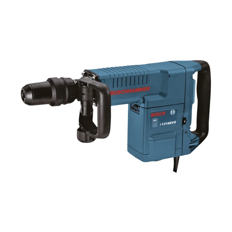
VARIABLE SPEED DIAL
Your tool is equipped with a variable speed
dial. The impact rate (BPM) and rotating
speed (RPM) can be varied according to the
type of work being performed by setting the
variable speed dial to the selected setting.
The chart below will help you to determine
which setting to use for your application.
However, a pre-test will determine the best
speed setting, as the chart is intended only
as a guide. Once the proper setting is
determined the impact rate and rotating
speed is kept constant by means of the
"Electronic Feedback Circuitry". The variable
speed dial can be adjusted while the motor is
running with the tool free from work, allowing
the operator to adjust the impact rate and
rotating speed according to the actual
application.
CHIPPING (DEMOLITION)
Area of application
Plaster work
Removing tiles
Brick work
Concrete
ELECTRONIC FEEDBACK CIRCUITRY
The internal electronic feedback system
provides a "soft start", which will reduce the
stresses that occur from a high torque start.
The system also helps to keep the
pre-selected impact rate and rotating speed
virtually constant between no-load and load
conditions.
INSTALLING ACCESSORIES
Clean the insert shank end of the accessory
to remove any debris, then lightly grease with
a light oil or lubricant.
Insert accessory into the tool holder through
the dust shield, while twisting and pushing
inward until it locks automatically into place.
Operating Instructions
Control setting
1 - 2
3
4
5 - 6
(EFC)
Pull outward on the accessory to be certain it
is locked into the tool holder (Fig. 2).
NOTE: The high efficiency available from
the rotary hammers can only be obtained if
sharp and undamaged accessories are used.
The "cost" to maintain sharp and undamaged
accessories is more than offset by the "time
saved" in operating the tool with sharp
accessories.
REMOVING ACCESSORIES
Accessories may be hot
after use. Avoid contact
with skin and use proper protective gloves or
cloth to remove.
To remove an accessory, pull and hold
locking sleeve backward and pull bit forward.
All accessories should be wiped clean after
removing.
FIG. 2
LOCKING SLEEVE
"VARIO-LOCK"- SELECTOR RING
The vario-lock selector ring can be set in any
one of twelve (30˚ increments) positions.
Choose a position which is best suited for
your operation. To adjust, pull the selector
ring forward and hold firmly, then turn both
the accessory and the selector ring to the
desired position. Release the selector ring
and turn the accessory slightly until it locks in
place.
-8-

