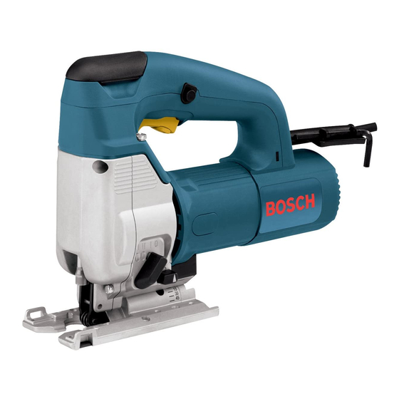
Bosch 1587AVSP-1 - 5 Amp Top-Handle Jig Saw Руководство по эксплуатации/безопасности - Страница 8
Просмотреть онлайн или скачать pdf Руководство по эксплуатации/безопасности для Электроинструмент Bosch 1587AVSP-1 - 5 Amp Top-Handle Jig Saw. Bosch 1587AVSP-1 - 5 Amp Top-Handle Jig Saw 33 страницы. Operating instructions
Также для Bosch 1587AVSP-1 - 5 Amp Top-Handle Jig Saw: Список деталей (3 страниц)

BM 2610993477 2-04
2/9/04
thin sheet metals and used with knife blades,
grit edge blades or rasp work.
Setting I soft materials where cleaner cutting
or delicate scrolling work is performed.
Setting II medium density materials such as
harder woods or particle board.
Setting III soft materials such as wood,
plastics, etc.
FOOTPLATE ANGLE ADJUSTMENT
The footplate may be tilted to allow angle cuts
up to 45˚ in either direction. To adjust
footplate, loosen screw (A) with allen wrench,
slide the footplate towards the front of the tool,
and rotate to the desired angle, as marked on
the angle scale. Detent slots will hold the
footplate firmly at 0˚, and there are additional
position marks for 15˚ and 45˚ angles.
SCREW (A)
FOOTPLATE
PROTRACTOR
(Not included)
FOOTPLATE INSERTS
(1587AVS & 1587DVS)
Model 1587AVS & 1587DVS will accept two
footplate inserts which may be changed by
removing the six screws (B). The steel insert is
used for most general cutting operations, and
the smooth plastic insert may be used to
minimize scratches on fine surfaces.
SCREW (B)
(1587AVS & 1587DVS)
ANTI-SPLINTER
INSERT
FOOTPLATE INSERT
(1587AVS & 1587DVS)
FOOTPLATE
9:24 AM
Page 8
The following types of blades should only be
used with orbital Setting O:
1. Blades with teeth that point downward
(reverse-tooth blades).
2. Blades with teeth that point straight out
rather than up or down.
3. Carbide-tipped blades.
4. Grit-edge blades.
Intermediate angles may be set with a
protractor. After positioning the footplate,
securely tighten screw (A).
On model 1587DVS, screw (A) is covered by
sliding cover, which should be closed after
making the footplate adjustment. Note that
when the footplate is used on an angle, dust
cover must be removed, and chip collection
efficiency will be reduced.
ANTI-SPLINTER INSERT
To minimize splintering of the top surface of
the material being cut, place the anti-splinter
insert in the blade opening of the footplate.
Note: This insert will only work with blades
that have ground sides such as T301CD,
T101B, T101D, and T101DP.
SCREW (A)
COVER (1587DVS)
-8-
DUST PORT
(1587DVS)
