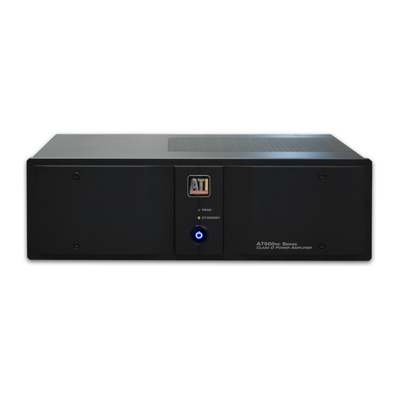
ATI Technologies AT525NC Руководство пользователя - Страница 6
Просмотреть онлайн или скачать pdf Руководство пользователя для Усилитель ATI Technologies AT525NC. ATI Technologies AT525NC 14 страниц. Class d 2 to 8-channel

Rear Panel Layout
A
B C
A. Balanced (XLR) Audio Inputs
Use the BALANCED INPUT jacks to connect to the
outputs of a preamplifier or other control device with
XLR outputs.
B. Unbalanced (RCA) Audio Inputs
Use the UNBALANCED INPUT jacks to connect to
the outputs of a preamplifier, receiver with preamp-
out connections, CD player, or other source device
with RCA style outputs.
C. Input Selector Switch
Selects either the BALANCED INPUT (XLR) or the
UNBALANCED (RCA) INPUT jack.
D. Remote Trigger Input
Use the REMOTE TRIGGER jack to connect to a
compatible preamplifier, source device, or other
product with a 3-24 VDC output.
Amplifier Channel To Speaker Map
AT500NC Manual
Amplifier Channel
CHANNEL 1
CHANNEL 2
CHANNEL 3
CHANNEL 4
CHANNEL 5
CHANNEL 6
CHANNEL 7
CHANNEL 8
E. Ground Terminal
Use to connect to other chassis where necessary.
F. Fuse
Replace only with the correct type and rating. The rat-
ing is shown on the rear panel next to the IEC power
inlet.
G. AC Inlet
Use the included power cord to connect your amplifier
to an AC power source.
H. Speaker Outputs
Use the OUTPUT binding posts to connect the amplifi-
er to your speakers. The post with the red band is posi-
tive. The post with the white band is negative.
Speaker
5
D
H
E
F
G
Rev-05/18
