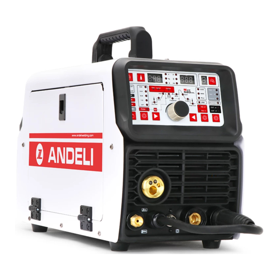
ANDELI MCT-520DPL Руководство пользователя - Страница 6
Просмотреть онлайн или скачать pdf Руководство пользователя для Сварочная система ANDELI MCT-520DPL. ANDELI MCT-520DPL 8 страниц. Multifuction welding&cutting machine
Также для ANDELI MCT-520DPL: Руководство пользователя (20 страниц)

MCT-520DPL
Fault symptom
The power indicator does not light, the fan does not
turn, no welding output
The power switch indicator is on, the fan does not turn
or rotates for a few times to stop, no welding output
The fan turns, the abnormal indicator light is not bright,
there is no high-frequency discharge "sa sa sa" sound,
and the "arc welding" can not start the arc.
The abnormal indicator light is not lit, there is a high-
frequency discharge "sa sa sa" sound, no welding
output.
Abnormal indicator light does not light, no high
frequency discharge "sa sa sa" sound, "LIFT TIG
welding" can start arc
Abnormal indicator light is on, no output
Can not break the oxide film when welding aluminum
Tungsten needle burnt seriously
Fault symptom
The fan does not rotate, the digital meter has no display, and there
is no welding output.
Remedy
1. The power switch is broken.
2. Confirm that the power grid connected to the input cable has power.
3. Check if the input cable has a break.
1. It is possible to input the wrong connection on the 380V power supply, causing the overvoltage protection circuit to
start, and then reconnect It to the 220V power supply and restart it.
2, 220V power is unstable (the input line is too long) or the input line is connected to the power grid, causing the
overvoltage protection circuit to start, increasing the wire diameter of the grid input line or fastening the input line node.
This phenomenon is in shutdown 2 - After 3 minutes, the new boot will return to normal.
3. Continuously open and close the power switch in a short time, causing the overvoltage protection circuit to start.
Wait for 2-3 minutes and then restart it.
4. The wires between the switch and the power board are loose and retightened.
5. The main circuit 24V relay on the power supply board is not connected or damaged, check the 24V power supply
and relay.
1. The voltage of the positive and negative poles of the VH-07 plug-in of the multimeter to the MOS board should be
about DC308V.
2. The auxiliary power supply on the MOS board has a green indicator light. If the light is not on, the auxiliary power
supply is not working. Look for the fault point or contact the dealer.
3. Check the poor connection of various patch cords in the machine.
4. Control circuit problems, find the cause or contact the dealer.
5. The control line on the welding torch is broken.
1. The welding gun cable is broken.
2. The ground wire is broken or not connected to the welded workpiece.
3. The positive output terminal or the welding torch gas output terminal is loose from the connection inside the machine.
1. The primary line of the arcing transformer has poor contact with the power board and is retightened.
2. The discharge nozzle is oxidized or the distance is remote. The surface oxide film of the discharge nozzle is treated or
the distance of the discharge nozzle is adjusted to 1 mm.
3. The Individual components of the high-frequency arc-ignition circuit are damaged, and the replacement found.
1. It may be overcurrent protection. Please turn off the machine. When the abnormal indicator light Is off and then
restarted, it can be restored.
2, may be overheat protection, do not need to shut down for 2-3 minutes, the machine can naturally return to normal.
3. It may be that the inverter circuit is faulty. Please unplug the power supply plug of the main transformer on the MOS
board (near the fan VH-07 plug-in) and restart it:
(1) If the abnormality indicator is still on, turn off the power plug of the high-frequency pilot arc power supply (near the
fan VH-03 plug-in) and turn it back on:
a. If the abnormal indicator is still on, the individual FETs on the MOS board are damaged.
b. If the abnormal indicator is not lit, the step-up transformer in the high-frequency arc-rising circuit on the power
supply board is broken and replaced. (2) If the abnormal indicator does not light:
a. It may be damaged in the middle plate transformer. The primary inductance and Q value of the main transformer can
be measured by the bridge,
b. It may be that the transformer secondary rectifier is individually broken down, and the same type of rectifier is found
and replaced.
4. It may be that the feedback circuit is open.
1. The welding gear selection is incorrect;
2. The duty cycle adjustment is too small;
3. The secondary inverter has field tube damage.
The duty cycle is adjusted too much to reduce the duty cycle.
Exclude
1. Confirm that the air switch is Intact or closed.
2. Confirm that the power grid connected to the output cable has power.
3. The thermistor (four) on the power supply board is damaged (this is usually caused by DC24V relay
failure or poor contact contact).
4. The power board (base board) is faulty and there is no DC537V voltage output.
