ATI Technologies M100 Руководство по эксплуатации и техническому обслуживанию - Страница 2
Просмотреть онлайн или скачать pdf Руководство по эксплуатации и техническому обслуживанию для Усилитель ATI Technologies M100. ATI Technologies M100 8 страниц. Ati ultimike m100 microphone amplifier operating and maintenance manual
Также для ATI Technologies M100: Руководство по эксплуатации и техническому обслуживанию (9 страниц)

GENERAL
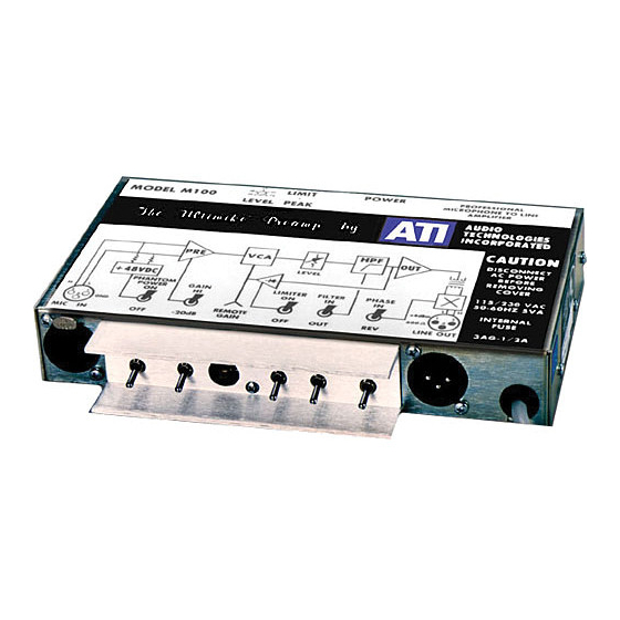
The ULTIMIKE M100 Microphone Amplifier is designed specifically to provide the
ultimate in no-compromise audio performance. A rugged, small AC line powered
amplifier, it may be placed close to the mike on the stage, in the pulpit or in the overhead
lighting structures to shorten sensitive low-level mike lines. Replacing your long runs of
low-level mike cable with high level feeds will greatly reduce your susceptibility to RF,
hash and hum pickup. In addition, the M100 is itself very well protected from both
radiated and conducted interference and has unmatched broadband common made
rejection to cancel microphone hum and RF pickup. A unique distortion-free transformer
coupled output provides total isolation of ground loops and ground voltage differentials
while simultaneously providing a low driving impedance to minimize high frequency
rolloffs due to excess cable capacitance.
To allow you to install the M100 close to the mike when necessary in what may be a
remote or poorly accessible location, we have designed the preamp to accept a very wide
range of input levels (up to 0 dBu) without input overload and we have incorporated a
switchable slow acting (but very low distortion) 24 dB limiter to turn down the output
level pot when you can't reach it.
In addition to all these modern conveniences, the ULTIMIKE is a superb performer with
ruler flat response, no ringing, excellent CMR, exceptionally low input noise, and trivial
distortion.
The ULTIMIKE amplifier is packed in a rugged, compact steel enclosure. All controls
and connecters are recessed for protection. Identification markings are printed on the
protected reverse side of a heavy duty polycarbonate overlay. All power supply
components are well shielded by the steel chassis.
Input mike level audio to the ULTIMIKE must run a gauntlet of ferrite suppressors,
bypass capacitors, DC blocking capacitors, and protection diodes designed to block the
trash, and transistors (Q1 and Q2) in an instrumentation amplifier configuration provide a
very low noise input gain stage. The balanced feedback network R12, R13, R20, and R
21 is driven from the outputs of A1A and A2A to eliminate any input loading that might
degrade common mode hum rejection and to allow use of low valued feedback resistors
for minim noise generation. Dual constant current stages (Q3 and Q4) sink DC emitter
current from Q1 and Q2 and allow complete servo cancellation of input offsets via
integrator A3A to maximize input stage headroom at A2B. A differential amplifier and
limiter are formed by A1BA2B. Common mode input signals are nulled out by R27 and
an LDR (light dependant resistor) in A2B's feedback loop reduces the input stage gain in
response to limiter levels. Even without limiting, the input stage will handle input levels
up to 0 dBm (gain – HI switch) or +20 dBm (gain –20 dB).
A3B forms a variable gain stage with a smooth logarithmic adjustment range of +37 to
–19 dB. R30, the level potentiometer, is screwdriver-adjustable through the front of the
amplifier. When rack mounted, the level adjustment is accessible through the panel.
Audio Technologies Inc. | 154 Cooper Road #902 | West Berlin, NJ 08091 | Voice 856-719-9900 | Fax 856-719-9903 | www.
audio.com
